Custom Bloom Post-Process in Unreal Engine
Making things shine the right way.
Making things shine the right way.
December 02, 2021
I wanted to see if I could modify the unreal engine bloom effect following my article on making custom lens-flare. This is because the default one can sometimes look disapointing and doesn't always behave the way I would expect. So I tried redo it to address those issues.
This article is written as a follow up of my previous one. I assume you already have a custom PostProcess plugin and know where to put the code and shaders.
This modification was tested with Unreal Engine version 4.25, but it should be applicable to version 4.26 and 4.27 as well. I didn't check with UE5 as it is still in early access.
Initially I didn't want to write a summary of what is bloom and why we simulate it, thinking it was obvious. Well, it isn't, and gathering some knowledge on the subject helped me understand a few things a bit better.
First of all, while "bloom" is a common term in realtime rendering, it isn't the primary keyword in research and optics. It is often referred as a disability/discomfort glare [1] or veiling luminance instead [2]. I was able to find a lot of interesting publications on the subject which I linked at the bottom.
Let me quote a few scientific papers:
"Bloom, frequently referred to as "veiling luminance" is the "glow" around bright objects. Bloom causes a reduction in contrast that interferes with the visibility of nearby objects [...]." [3]
"Glare is caused by bright sources in the visual periphery, which scatter light in the lens of the eye, obscuring foveal vision. Color sensitivity is reduced in dark environments, as the light-sensitive rods take over for the color-sensitive cone system."
"Visual acuity, the ability to resolve spatial detail, is also impaired in dark environments, due to the complete loss of cone response and the quantum nature of light sensation."
"Bright glare sources in the periphery reduce contrast visibility because light scattered in the lens obscures the fovea; this effect is less noticeable when looking directly at a source, since the eye adapts to the high light level." [4]
There is also an interesting publication about simulating the glare effect of the human eye [5]):
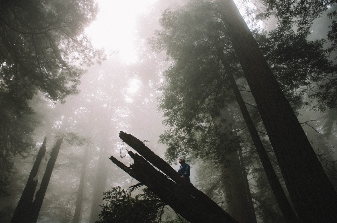
Now here is what bloom looks like from a camera viewpoint:
(Captured with my old FinePix S1800 with two LED light sources.)
A camera behavior is close to the human eyes, which is why bloom can be seen with them as well (but slightly differently).
Light rays entering a camera lens get scattered because of imprecisions, defects with the internal glasses or simply because of dirtiness. The light source becomes less defined which leads to a blurry image since the rays are not concentrated into a single point anymore. This generates a glare (and even ghosting).
The sensor, the part that converts the energy into an information, can also get overwhelmed. It means the electric charge received in the sensor grid can bleed into neighbor cells, leaking information.
In computer graphics, bloom can also be a way to simulate very cheaply atmospheric scattering of lights (like a lamp post in the fog).
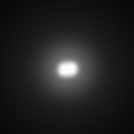
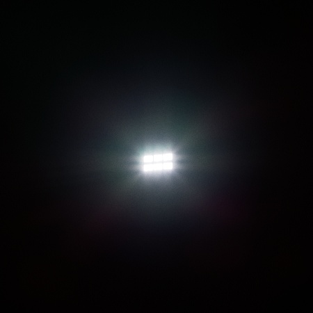
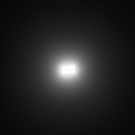
Here are some additional examples:
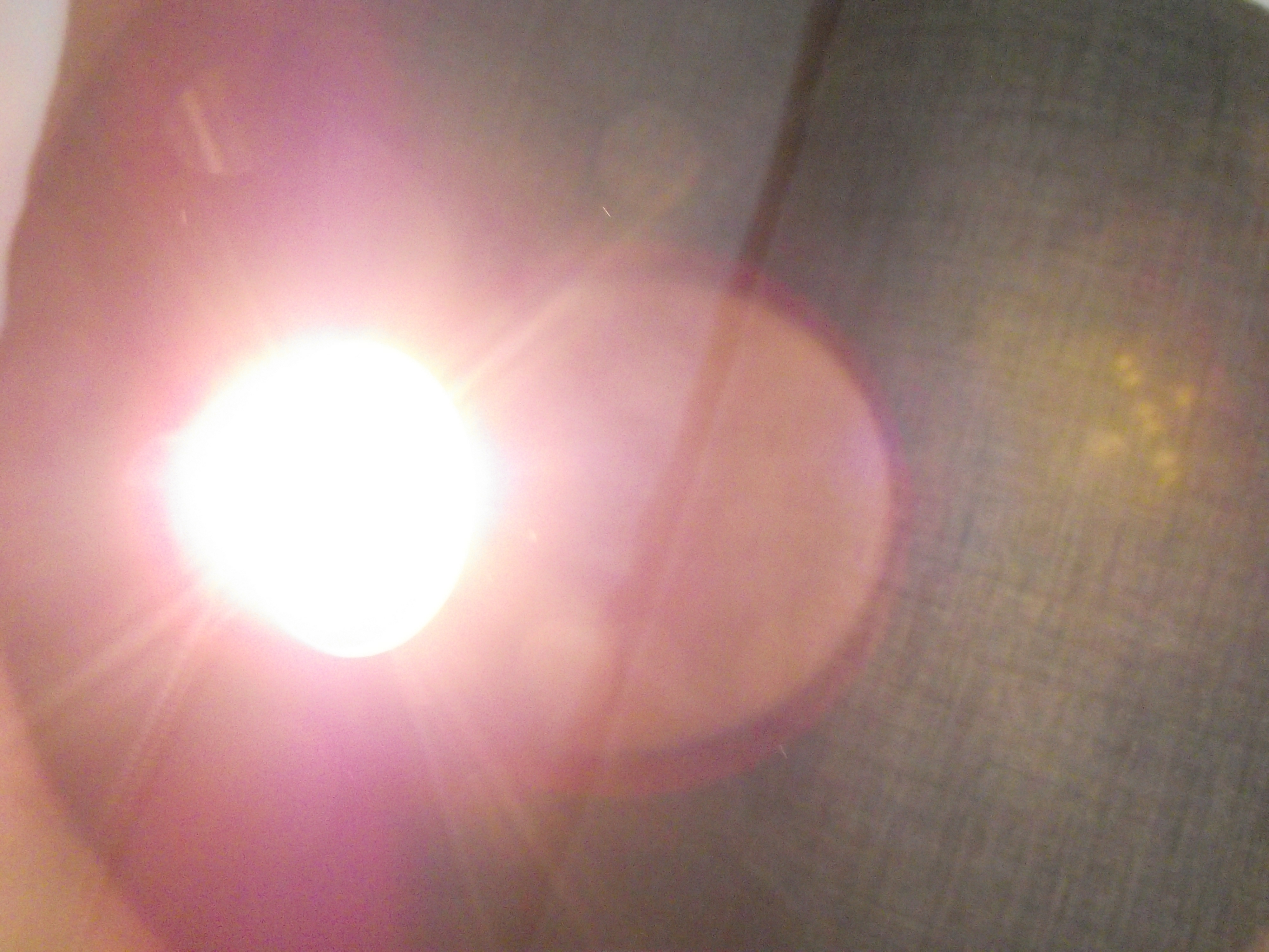
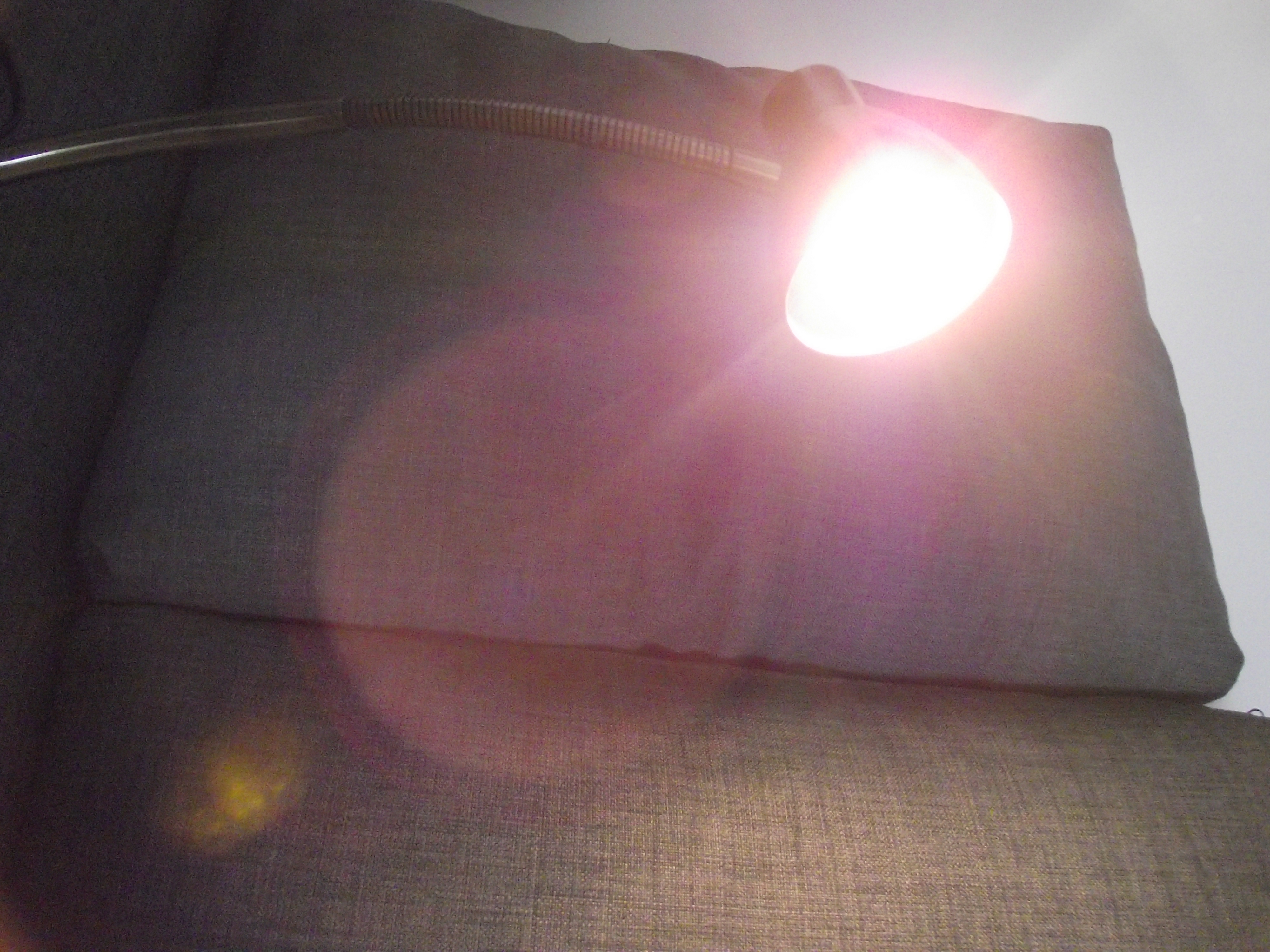
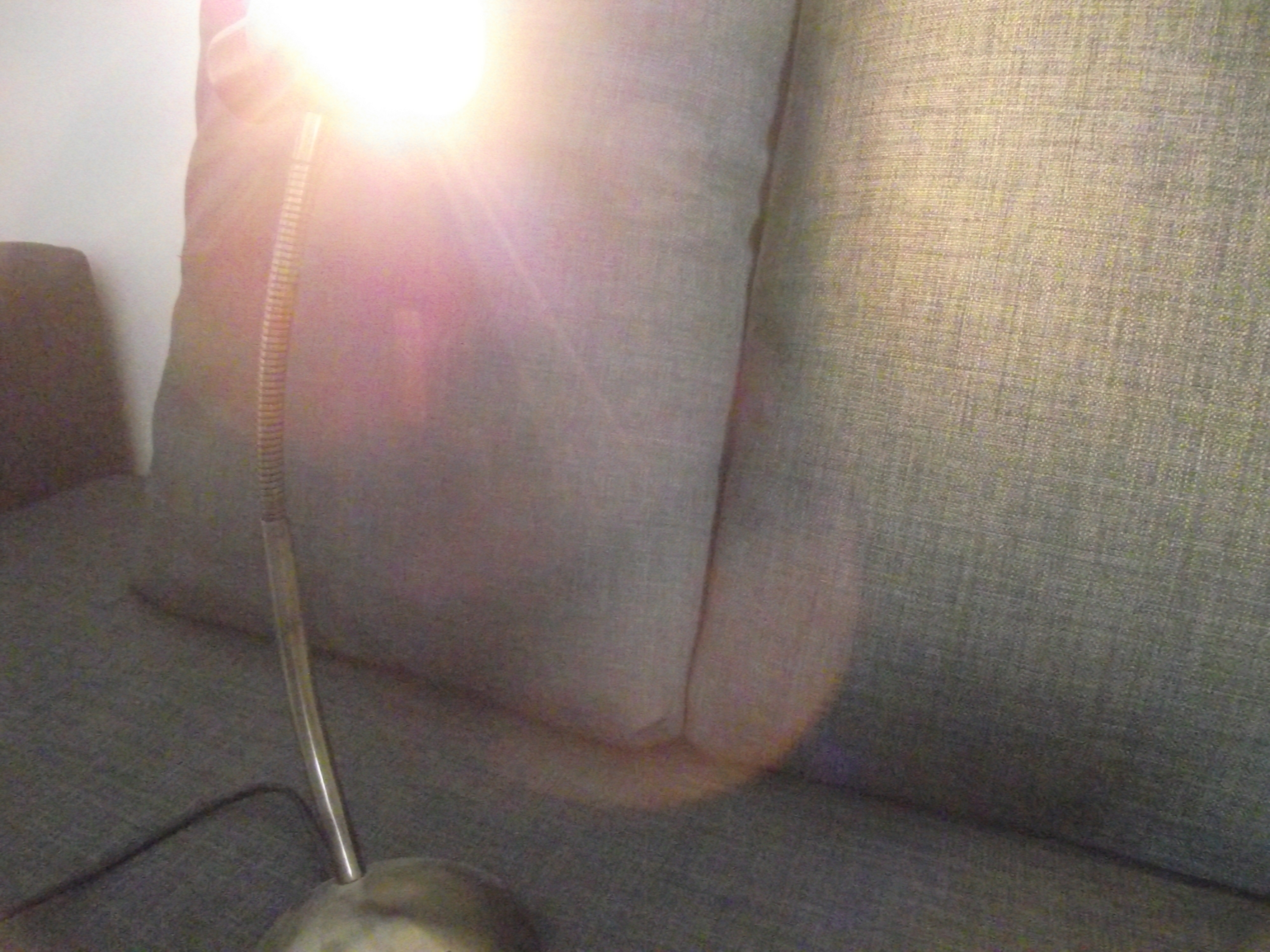
(Lens-flare and glare from my desk lamp.)
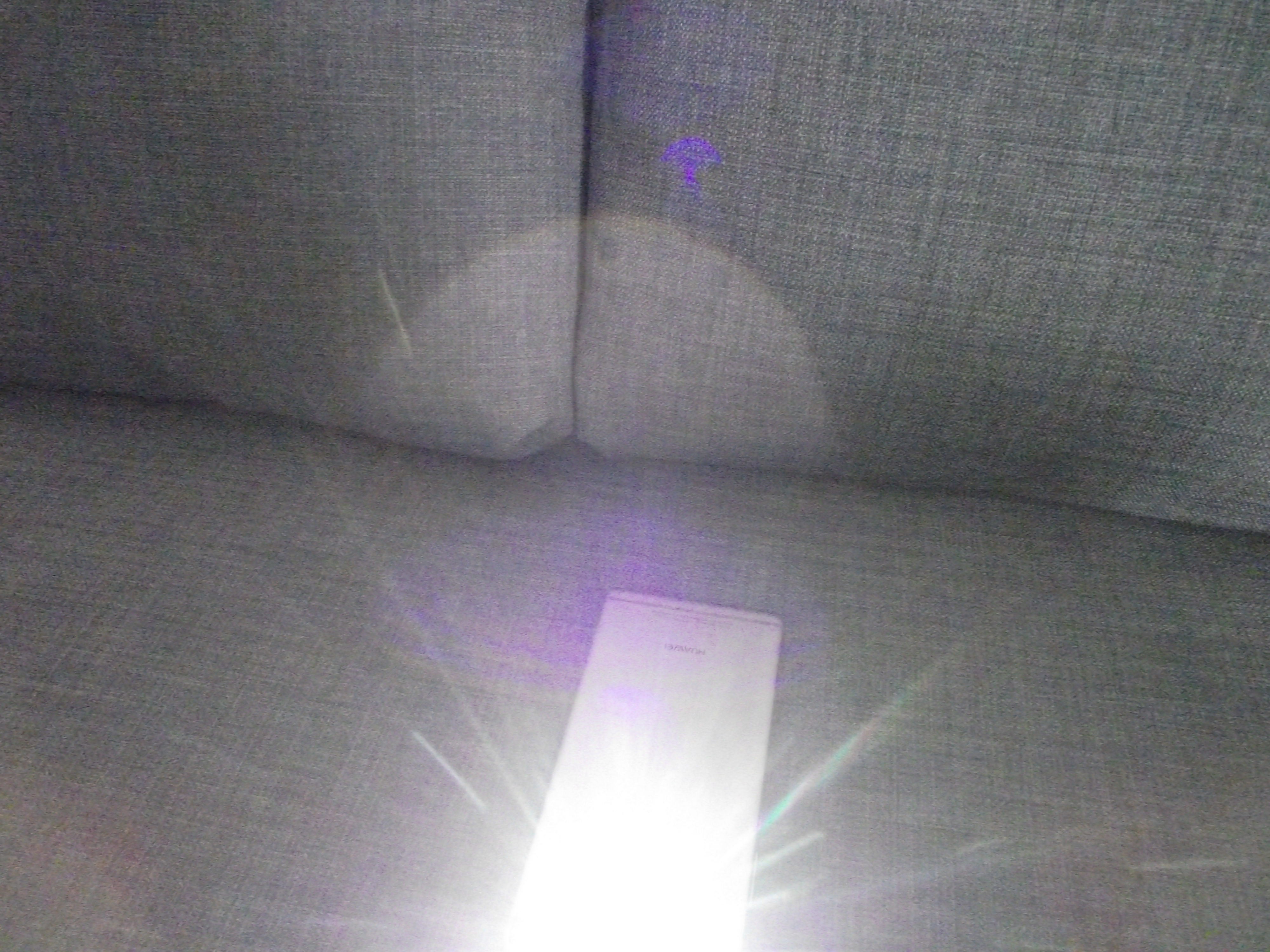
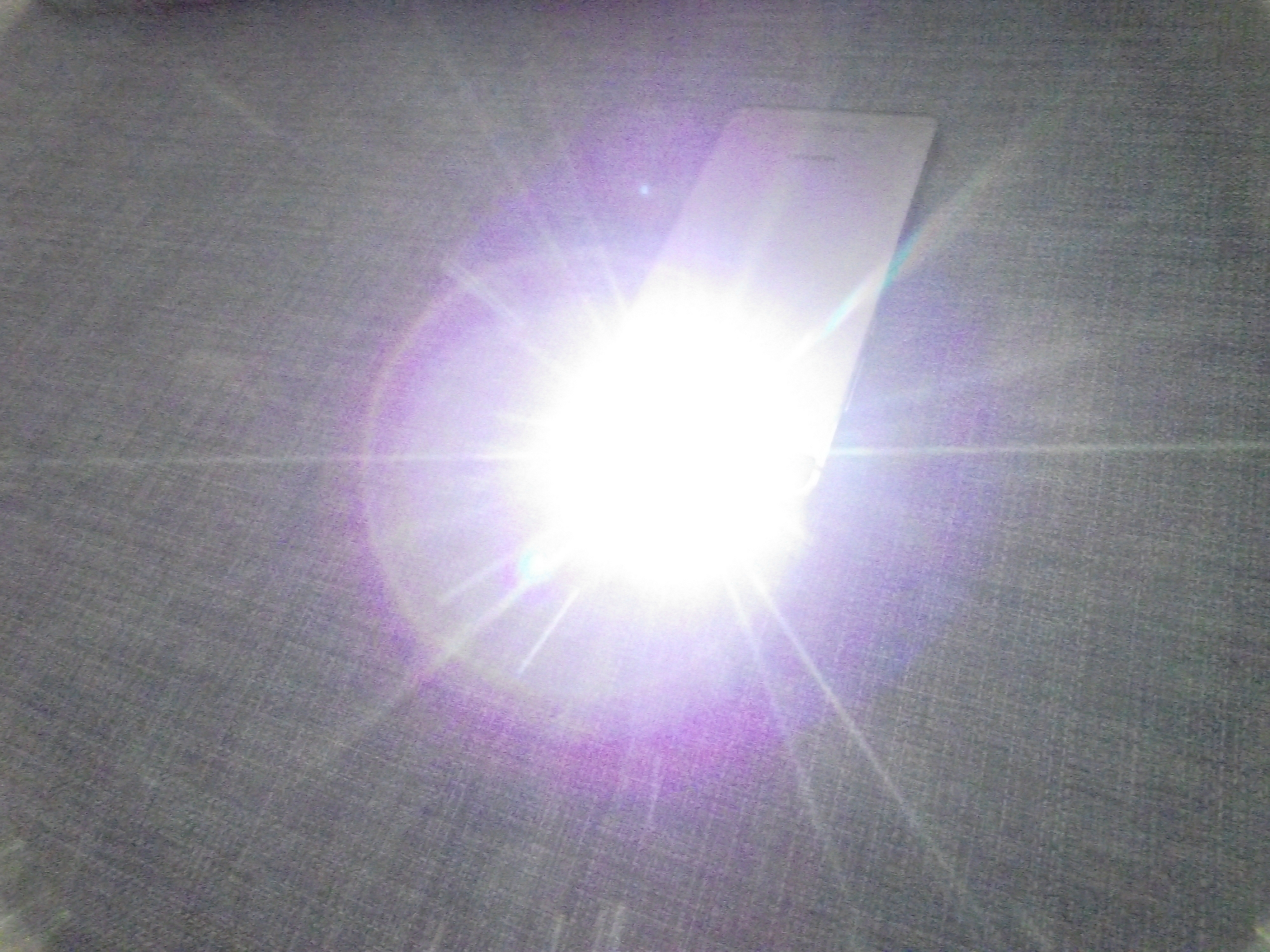
(Lens-flare and glare from my phone flashlight.)
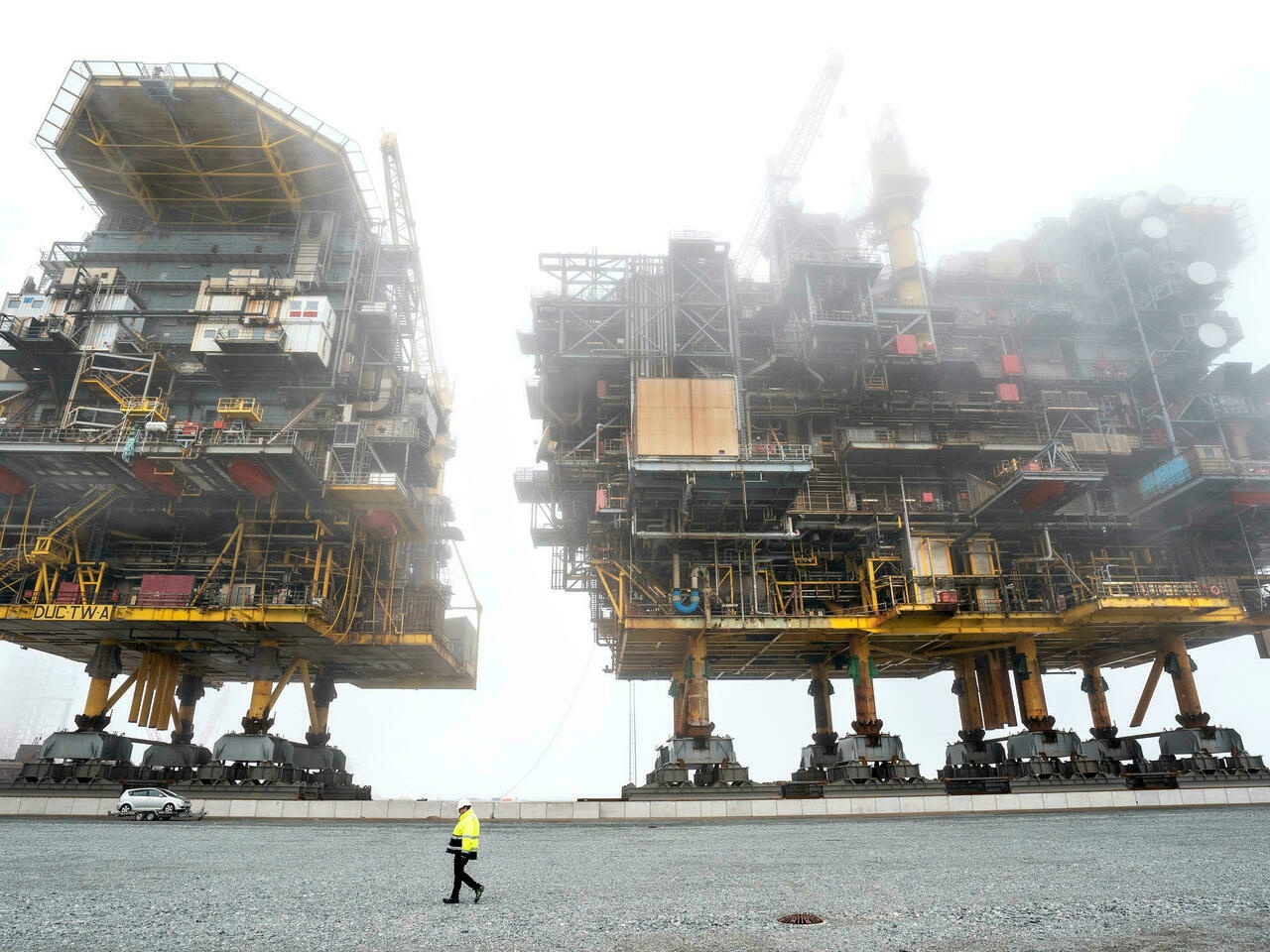
(Heavy fog scattering the bright sky.)
So long story short, bloom is a visual effect that signifies a light is very bright since it overwhelms our sensors (eye or camera). We simulate it to replicate this blindness in order to increase the fidelity/natural look of our computer generated image.

"My eyes !"
In Unreal Engine there are two types of Bloom: Standard and Convolution.
(Standard vs Convolution)
I won't linger on the convolution based bloom, it's a high-end post-process that isn't meant for realtime. It might become more affordable in the future with UE5 [6] but for now it's not really usable.
Instead, my focus went on the more traditional effect. Like mentioned in the introduction, there is something that always bothered me about the default bloom in UE4, especially after comparing it with others made in more recent games.
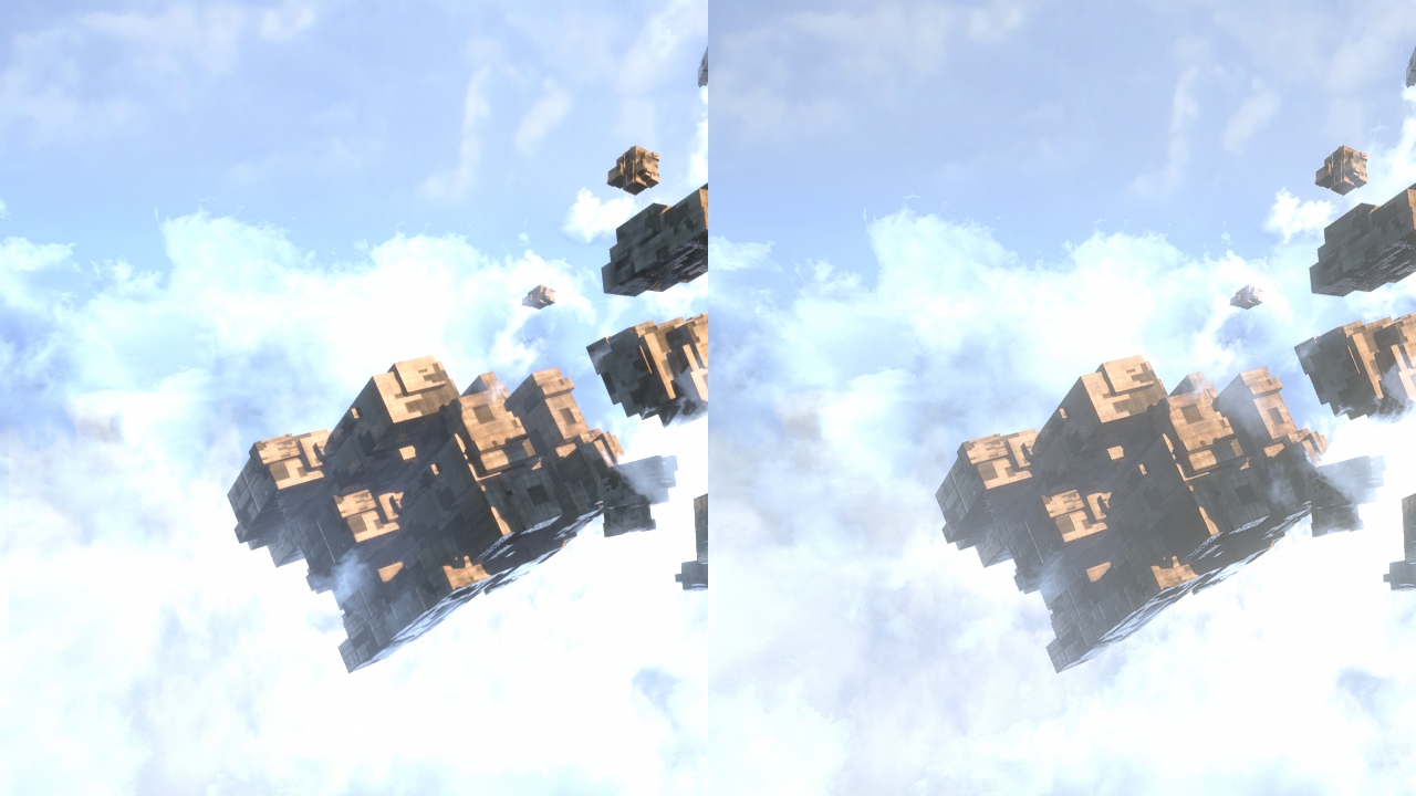
Here is a side by side of the existing effect against my own version:
(Old vs New)
In order to compare properly the old method and the new one, I made the tints of the old bloom white (they are different level of gray by default). This helps compare the actual blur shape and accentuate the issue I have with the old one: the strong glow around the light source and then the quick fade of its tail.
It can be hard to notice the difference without a properly calibrated monitor. So to be sure I wasn't hallucinating I did a cross section comparison to observe the shape of the gradient more easily:
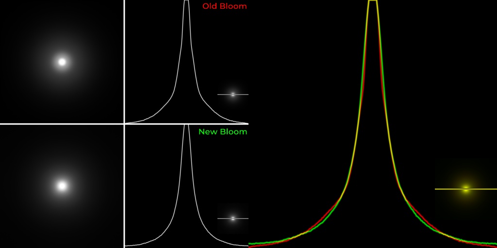
As you can see, the old bloom doesn't have a smooth curve, some angular transitions are visible.
It is very likely that this shape is intentional (more on that later) but I find it very displeasing. In contrast, the new method use a different way to build its result giving a much more continuous gradient.
To understand the UE4 bloom, let's go over how the effect is often made and mixed into the final image. In many games it is done as follow:
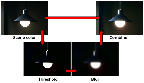
(Overview of the most common process. [7] [8])
Those are very crude steps, but they raise severals questions in my head: why using thresholding ? Why using and additive blending ? Why blurring, and how ?
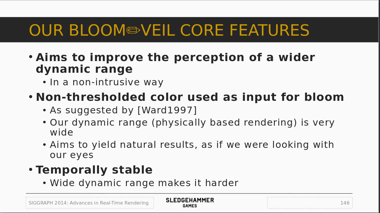
The idea with thresholding is to only keep the very bright areas of the image to contribute to the bloom. This is an easy way to make bright lights stand out without having to deal with unexpected illuminations (like having the floor or the head of a character bleed everywhere).
However, having something less to worry about is always beneficial when calibrating visuals. The advantage of having no threshold helps in creating content that reacts more naturally (since pixels can properly fade in and out in intensity). In real life there is no thresholding, so having lighting and visuals react in a similar way can help improve fidelity.
No thresholding also means we don't have to compute it, so we can save a bit of performance on that too.
So why do we need to blur ? Like I explained previously, as light scatter, it spreads and the source image becomes less precise/defined.
Okay, but why is it done with a Gaussian blur [10] (and not a blur based on another distribution) ? It is because reality is already close to that:
"For the cornea and the lens, the light is scattered in a narrow forward cone with approximately a Gaussian distribution."
"The corneal scattering can be differentiated from the lenticular scattering since it casts a shadow of the iris on the retina. The retina to retina scattering, although physically in all directions is only important in the same forward directions due to the drastically reduced directional sensitivity of the cone system to obliquely incident light [...]."
"Because the rod sensitivity does not have as high a directional sensitivity as the cones, the magnitude of glare is greater in dark (scotopic) conditions. For these reasons, the light scattering is somewhat like a "blurring" or "blooming" effect with a sharp drop-off, and can be approximated with empirical formulae to match the experimental results." [3]
I didn't check in other publications, but I presume cameras behave in a similar way because the sensor that registers the light information is at the end of the camera lens. Or maybe because of the Airy Disk, which can be approximated with a Gaussian distribution as well. [11]
However, I wasn't able to find any games/realtime publications that referenced this kind of research, so I wonder if using a Gaussian blur was chosen a bit by habits in the end simply because it was common in computer graphics for processing images.
Since a Gaussian blur is separable, meaning it can be computed in two simple steps instead of a single complex one, this makes it very appropriate for a GPU based implementation [12].
When the bloom has been generated, it is added back into the scene color usually as a simple additive color. This is usually fine because colors are often managed in HDR and then gets tonemapped, so they won't clamp in an ugly way.
However additive blending in this context isn't physically correct. By adding the bloom we make bright pixels even brighter and since the blur make them bleed across multiple pixels it end ups brightening other areas of the image as well. This can skew how the content of a scene can look and even be tricky to balance in dark ambiances.
So we need an alternative method to blend the blur into the original image without increasing its intensity along the way. A linear interpolation is a simple and good alternative. It also means that we cannot use a thresholded image since otherwise we could potentially blend with darker pixels and loose the original image intensity.
The standard bloom in UE4 barely changed since its introduction in 2012 for the Elemental demo [13]. The idea is to do a wide Gaussian blur while leveraging the way a GPU works to keep it cheap to render:
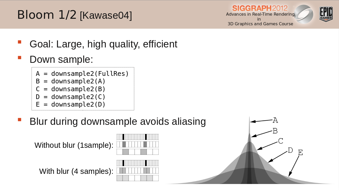
The process works by reducing the scene color size multiple times (downsampling), using the previous result each time. While reducing it averages multiple pixels to slightly blur the result. This is done to reduce aliasing but also provide temporal stability (4 pixels are sampled for 1 given pixel, aka 2x2 box). The sampling position is in-between pixels to take advantage of bilinear filtering.
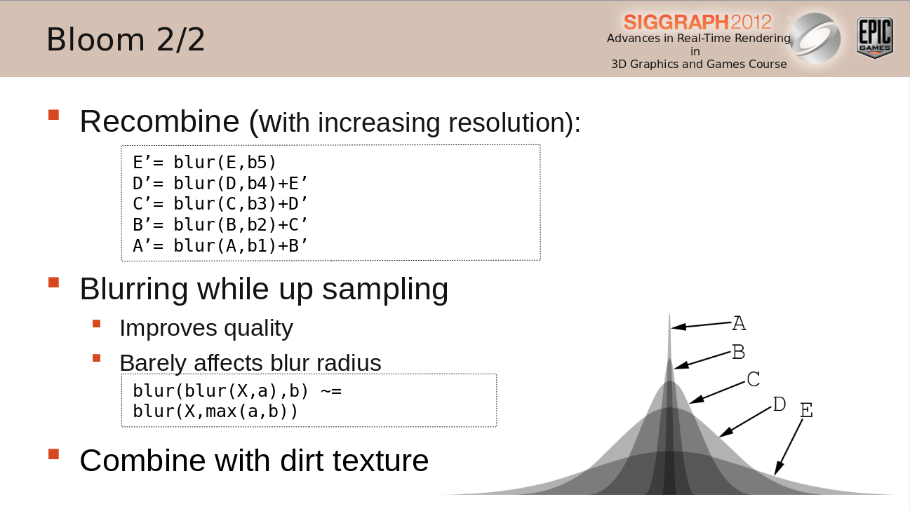
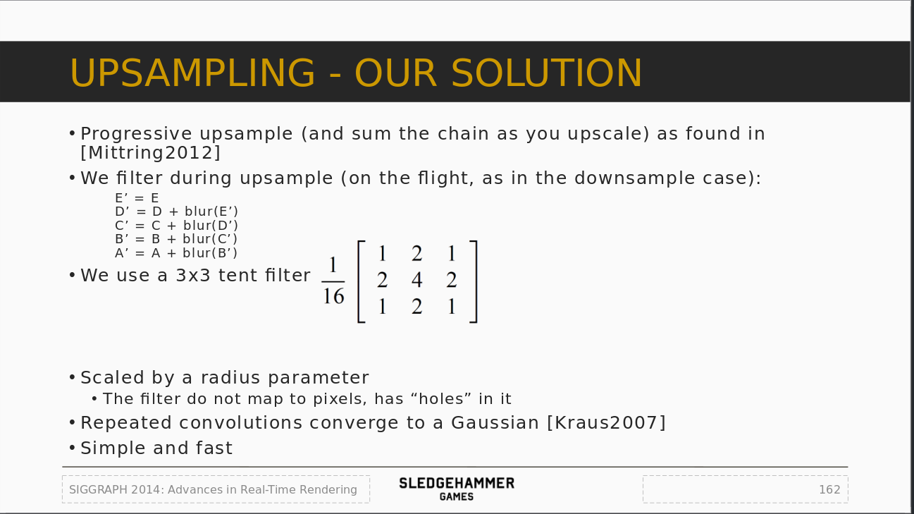
The next step consist of going back from the smallest texture to the biggest one, by upsampling the textures along the way. The upsample rendering works by combining the previous texture with the current one that was blurred with a separable Gaussian blur (meaning the image is blurred on one axis, then the result is blurred along the other axis).
Another important point to note is that the number of downsamples is fixed at 6 (at maximum scalability level). This is problematic because when you increase resolution, the blur size will be reduced because of the starting resolution. This is why when rendering at 1080p vs 4K it won't look the same unless manually compensated with the blur size (which by the way may not be enough or even more expensive than doing another downsample).
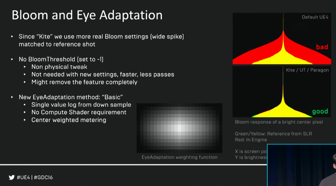
Epic Games also showed that the actual shape of the bloom captured on a DSLR is actually a "very thin spike" [14]. However they haven't provided more details (neither the camera model or their method of measurement/capture) which make this information a bit nebulous to work from.
On the bright side (hehe), we can compare the Unreal Engine versions to see how the bloom post-process settings evolved.
Defaults values in version 4.7:
Default values in version 4.8:
The bloom threshold got removed (it is disabled when set to -1), the intensity adjusted to match the new blur sizes and tints. Each tint correspond to one of the blurred downsample buffers (which switched from 5 to 6 steps).
I put theses in a graphs (made with Desmos) to get an idea of what the bloom shape looks like:
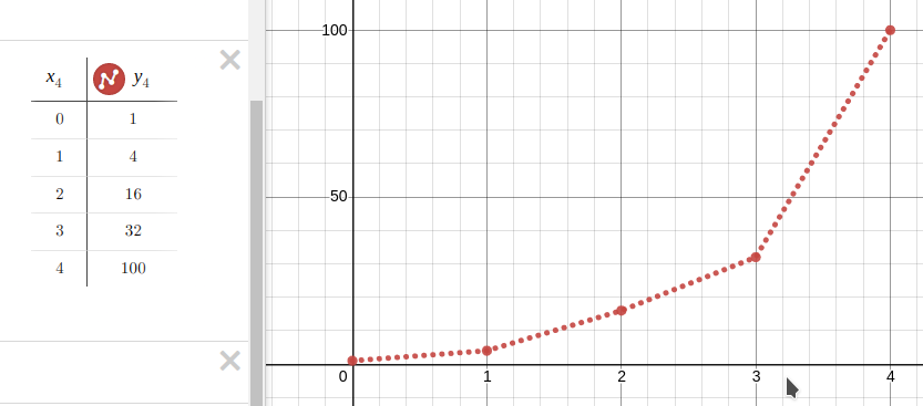
(UE4 bloom size in 4.7)
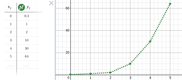
(UE4 bloom size in 4.8)
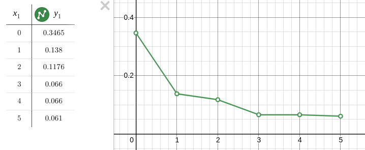
(UE4 bloom tints in 4.8)
Unfortunately it is hard to get a proper idea of the shape just from these. So I used a different process for the matching (detailled further down).
In Call of Duty Advanced Warfare [15] the developers used a method inspired from the one in UE4:
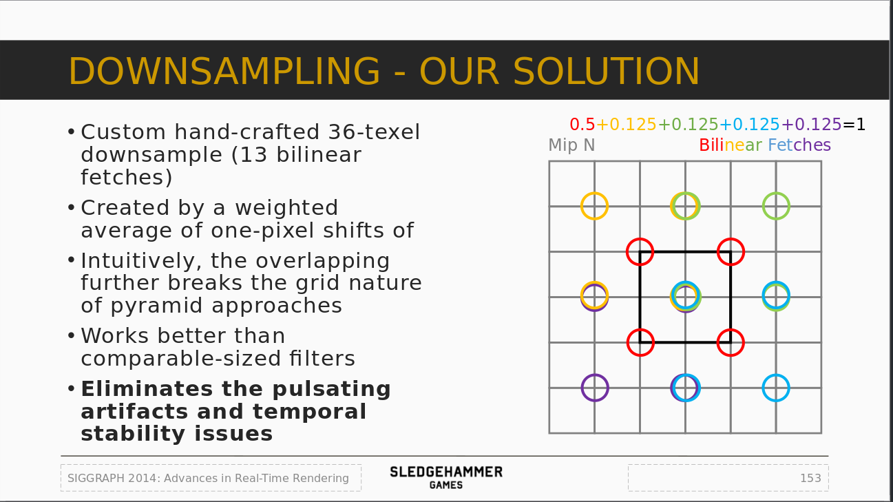
The idea is still to perform the series of downsamples then upsamples, but instead of doing a 2x2 box filter, they use a custom 13 samples pattern for the downsample and 9 samples pattern for the upsample to improve the stability of the effect. Like in Unreal, each upsample pass also uses an intermediate blurred buffer.
My method is inspired by the one from Call of Duty, meaning I use the same downsample/upsample patterns, but I removed the intermediate blur passes.
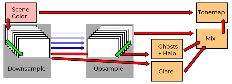
(Quick overview of my method.)
The process works in 8 steps (8 downsamples then 7 upsamples), but in practice I only do 7 downsamples because the engine already provide the first downsample (the scene color at half resolution).
8 steps give a very wide blur that can match the original UE4 bloom size. Since I'm skipping the intermediate blur passes, performance stay very good as generating small textures is quite cheap.
This number of steps should be tied to the screen resolution. At 720p 8 steps are likely too much, while at 4K a they might not be enough. However I didn't want to spend time on trying to find a forumla to adjust the number of steps.
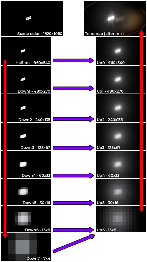
(Overview of the process. The thumbnails above have been manually tonemapped for better viewing.)
(Little animation of the process.)
The downsample process is simple because it just reads the previous result and write the new one at a smaller resolution. With the provided pattern it slightly enlarge the image at each new pass.
The upsample is slightly different because it reads the previous upsample (and use the sampling pattern to upscale it) and combine it at the resolution just above with the the current downsample. The next pass go up a resolution and redo the same process.
To combine the upsamples, passes are blended together with a linear interpolation. This allows to control the wideness of the blur by changing the weight of the blend.
Like I previously explained, I don't rely on thresholding. The whole screen is blurred no matter what and contributes to the final bloom. The result of the bloom process is composited with the scene color inside the tonemapper pass using a linear interpolation (lerp()) in the shader. See below for some comparisons.
I based this idea on the bloom effect made by Cody Darr (Sonic Ether) which showed interesting results this way. [16]
When reading a texture in a shader we can specify different ways to read the pixels. There is both mignification and magnification filters as well as the wrap parameters.
For the filters I simply use the regular bilinear filtering, that allows to sample multiple pixels at the same time with the help of the hardware resources. For the wrapping I could choose between a few:
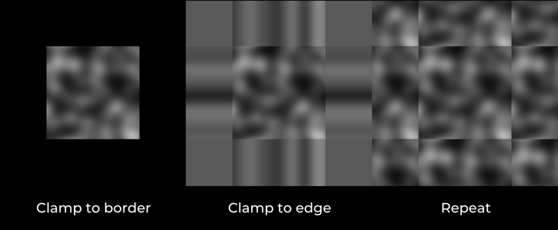
Here is what happens if I use each mode during the downsample and upsample passes:
(Clamp to border)
(Clamp to edge)
(Repeat)
The first example is how the bloom in UE4 behaves already: since the pixels sampled outside of the screen are black, this contribute to making the pixels at the edges less bright because of the sampling pattern. It produces this kind of fading noticeable in the corners.
The second example shows how overly bright the bloom is because of the opposite effect to the previous example: pixels at the edges are repeated so their value get incorrect because of the sampling pattern and increase in brightness. So any bright pixel at the edge will act as if there was an infinite bright light outside the screen.
The third example just shows how repeating the texture doesn't work for screenspace effects (but mirrored wrapping could be an alternative).
In all these examples I used the same wrapping during the dowsammple and upsample process, but since I was curious I played a bit with the parameters and found a result that I liked better by mixing them:
(Once again, clamp to border for both the downsample and upsample to help compare.)
(This time clamp to border for the downsample and clamp to edge for the upsample.)
This hybrid mode still gives a smooth fade at the edges when the bright area disappear, but it doesn't produce the odd corner fading.
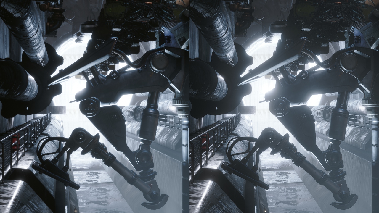
Here is another example:
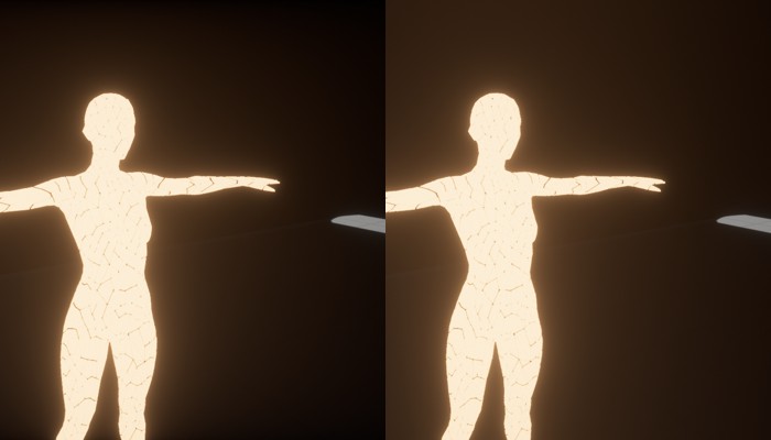
Both setups have they pros and cons, but personally I prefer the result on the right which seems to work better in most cases.
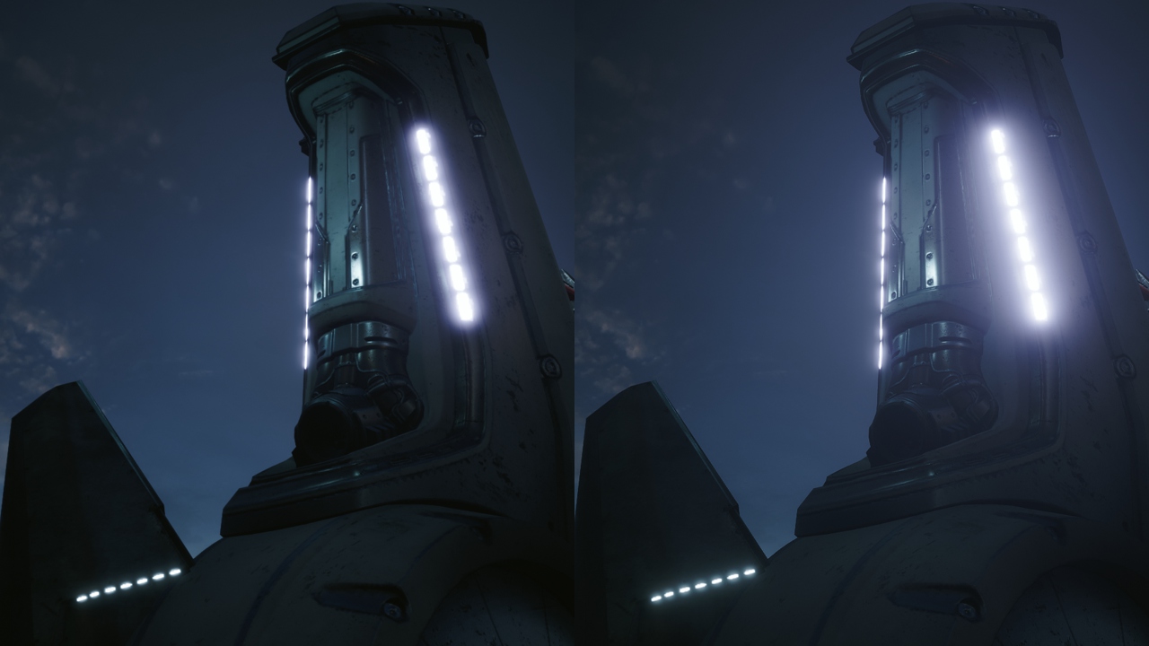
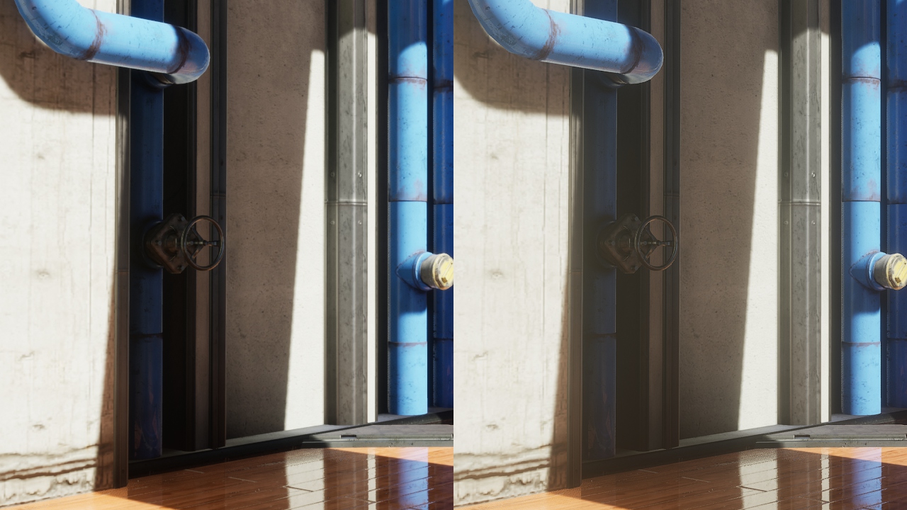
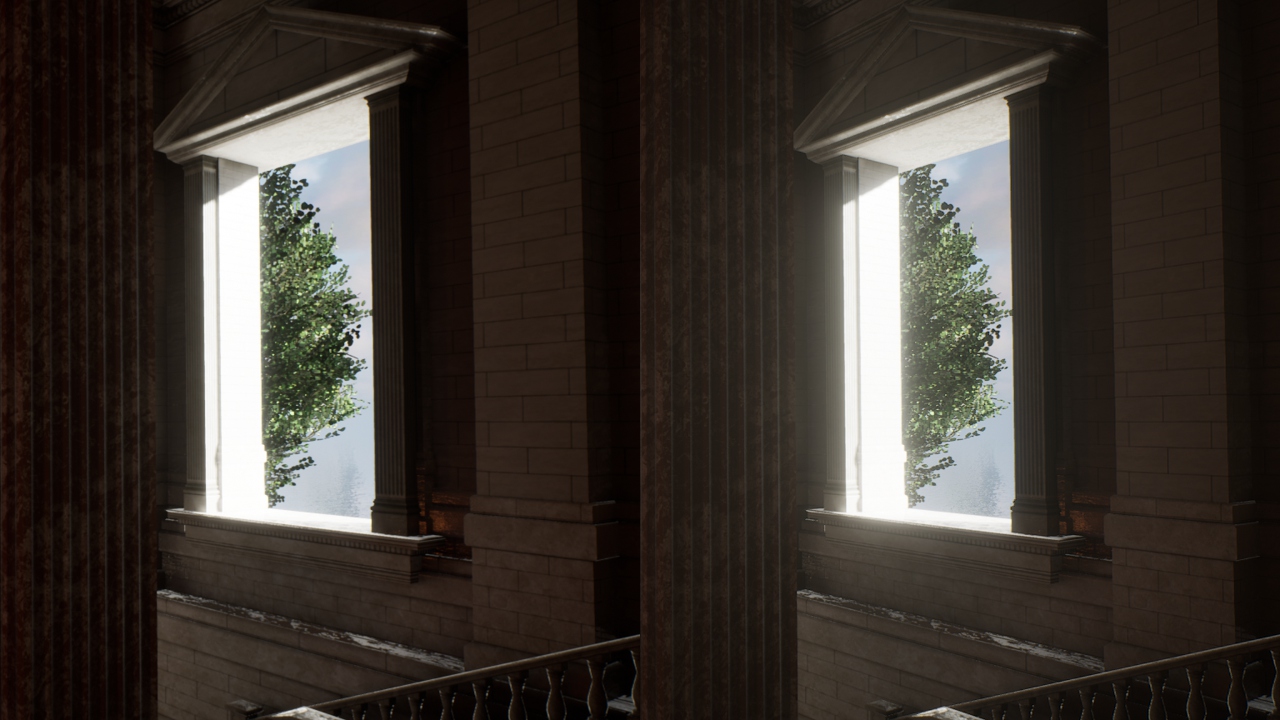
Now here is a series of comparisons between the old effect and the new one across a few projects:
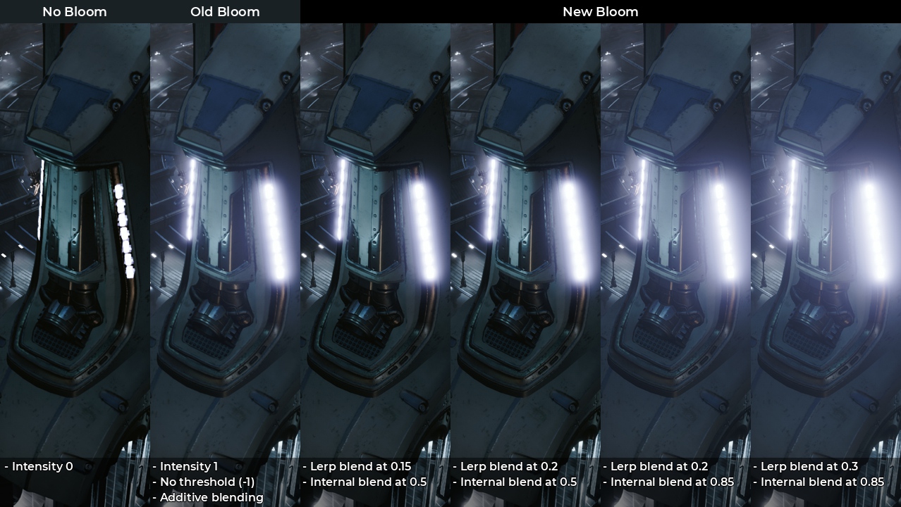
Little explanations of the legends:
What I find interesting is seeing how the default bloom seem so heavily focused and then fade very quickly in intensity. The fact it is additive also slightly brighten the image.
On the other end, with a focused/small bloom, you can see my own effect doesn't brighten the image. Using a wider radius means that low lights lose intensity quickly while bright lights will spread further away.
An internal blend of 0.5 gives quite a neutral shape to the bloom, but to match better a Gaussian blur I found that a value between 0.7 and 0.85 usually works better. This make bright lights very wide however, so you may have to adjust your content to compensate that (by using less intensive emissive surfaces for example).
Note that having a wide tail is also possible with the original UE4 bloom by adjusting the tints.
I made a simple scene with a bright emissive sphere, captured a screenshot, then used a cross section to compare the trail of each bloom (old vs new). This allowed me to match the original bloom trail by adjusting the internal blend value:
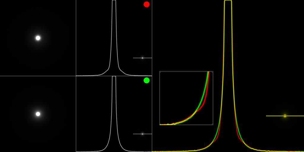
A few more comparisons between the default method and my own (using the blends 0.3 for tonemap and 0.85 for internal):
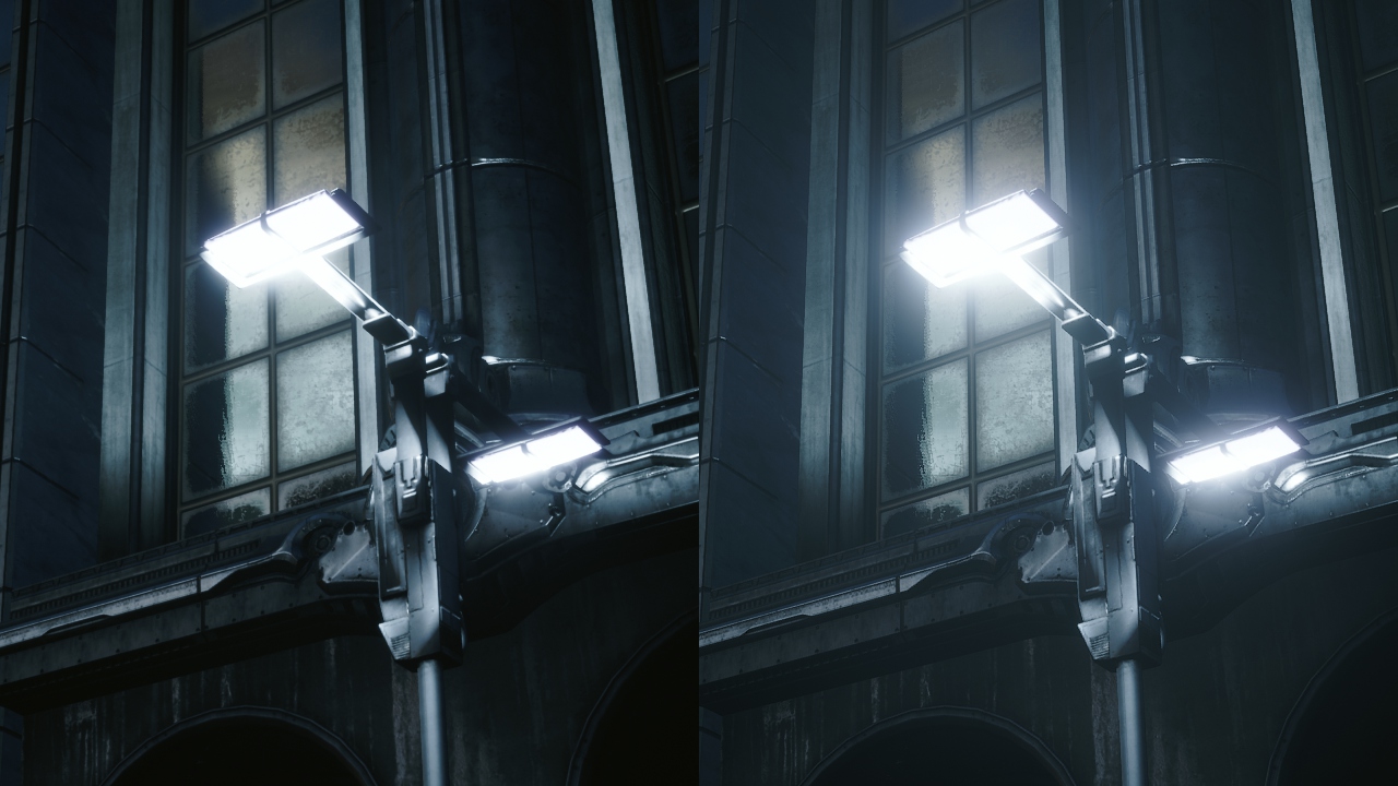
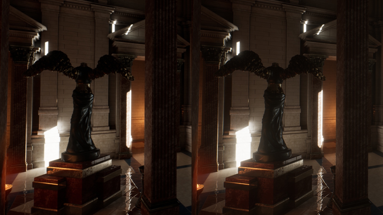
Even with a more intense/wider bloom you can see the new method doesn't clamp the whites and gives a softer result that is more pleasant to look at.
Once again, be sure to read my Lens-Flare article before going further as I'm basing my explanations on top of it.
This time I completely override the bloom and lens-flare rendering, which is different from before. Overriding both has the advantage of reducing the amount of files to modify since we can branch out much more early in the code.
Open up Engine/Source/Runtime/Renderer/Private/PostProcess/PostProcessing.cpp and on the first lines, just after the includes, add this new delegate:
[...]
#include "PixelShaderUtils.h"
#include "ScreenSpaceRayTracing.h"

DECLARE_MULTICAST_DELEGATE_FourParams( FPP_CustomBloomFlare, FRDGBuilder&, const FViewInfo&, const FScreenPassTexture&, FScreenPassTexture& );
RENDERER_API FPP_CustomBloomFlare PP_CustomBloomFlare;
This will be the delegate function that will allow us to hook our plugin into the engine process. Its layout is as follow:
In my previous article I used to define a custom struct to send back and forth my new RenderGraph texture and its size property. It's only after publishing my article that I noticed that the engine already has such struct, the FScreenPassTexture, and it can be used anywhere.
So from now one I'm using this struct to share and return textures which simplifies my code quite a bit.
Next go down a few lines to reach the namespace, and add the following cvar:
namespace
{
//-----------------------------------
// Froyok
TAutoConsoleVariable<int32> CVarPostProcessingCustomBloomFlare(
    TEXT("r.PostProcessing.CustomBloomFlare"),
    1,
    TEXT("If enabled, use external Bloom/Lens-flares rendering"),
    ECVF_RenderThreadSafe);
//-----------------------------------
This cvar will be used to easily switch between the old bloom and the new one. Note that by default it is set to use the new bloom.
Scroll down further until you reach if block starting with if (bBloomEnabled) looking like this:
        if (bBloomEnabled)
        {
            FSceneDownsampleChain BloomDownsampleChain;

            FBloomInputs PassInputs;
            PassInputs.SceneColor = SceneColor;

            const bool bBloomThresholdEnabled = View.FinalPostProcessSettings.BloomThreshold > -1.0f;

            // Reuse the main scene downsample chain if a threshold isn't required for bloom.
            if (SceneDownsampleChain.IsInitialized() && !bBloomThresholdEnabled)
            {
                [...]
            }
            else
            {
                [...]
            }

            FBloomOutputs PassOutputs = AddBloomPass(GraphBuilder, View, PassInputs);
            SceneColor = PassOutputs.SceneColor;
            Bloom = PassOutputs.Bloom;

            FScreenPassTexture LensFlares = AddLensFlaresPass(GraphBuilder, View, Bloom, *PassInputs.SceneDownsampleChain);

            if (LensFlares.IsValid())
            {
                // Lens flares are composited with bloom.
                Bloom = LensFlares;
            }
        }
Encompass the code inside another if() block. This will be our way to hook our own process:
        if (bBloomEnabled)
        {
            // Froyok
            if( !CVarPostProcessingCustomBloomFlare.GetValueOnRenderThread() )
            {
                FSceneDownsampleChain BloomDownsampleChain;

                FBloomInputs PassInputs;
                PassInputs.SceneColor = SceneColor;

                const bool bBloomThresholdEnabled = View.FinalPostProcessSettings.BloomThreshold > -1.0f;

                // Reuse the main scene downsample chain if a threshold isn't required for bloom.
                if (SceneDownsampleChain.IsInitialized() && !bBloomThresholdEnabled)
                {
                    [...]
                }
                else
                {
                    [...]
                }

                FBloomOutputs PassOutputs = AddBloomPass(GraphBuilder, View, PassInputs);
                SceneColor = PassOutputs.SceneColor;
                Bloom = PassOutputs.Bloom;

                FScreenPassTexture LensFlares = AddLensFlaresPass(
                    GraphBuilder,
                    View,
                    Bloom,
                    *PassInputs.SceneDownsampleChain
                );

                if (LensFlares.IsValid())
                {
                    // Lens flares are composited with bloom.
                    Bloom = LensFlares;
                }
            }
            else
            {
                // Call the delegate functions
                // This will run the rendering code from our Plugin
                PP_CustomBloomFlare.Broadcast( GraphBuilder, View, HalfResolutionSceneColor, Bloom );
            } // End CVarPostProcessingCustomBloomFlare

        }
As mentioned above, this override both the bloom and the lens-flares code. This is because I ended up combining my bloom process with my custom lens-flares. I didn't want to to cover how to only override the bloom as several adjustments of the original code need to be done.
Next step is to change the way the bloom is blended inside the tonemapper. So open the file Engine/Shaders/Private/PostProcessTonemap.usf to adjust the compositing. Start by adding the new parameter at the beginning of the file:
Find the following code:
            #if FEATURE_LEVEL == FEATURE_LEVEL_ES3_1
                // Support sunshaft and vignette for mobile, and we have applied the BloomIntensity and the BloomDirtMask at the sun merge pass.
                LinearColor = LinearColor.rgb * CombinedBloom.a + CombinedBloom.rgb;
            #else
                float2 DirtLensUV = ConvertScreenViewportSpaceToLensViewportSpace(ScreenPos) * float2(1.0f, -1.0f);

                float3 BloomDirtMaskColor = Texture2DSample(BloomDirtMaskTexture, BloomDirtMaskSampler, DirtLensUV * .5f + .5f).rgb * BloomDirtMaskTint.rgb;

                LinearColor += CombinedBloom.rgb * (ColorScale1.rgb + BloomDirtMaskColor);
            #endif
        #endif
And turn it into:
            #if FEATURE_LEVEL == FEATURE_LEVEL_ES3_1
                // Support sunshaft and vignette for mobile, and we have applied the BloomIntensity and the BloomDirtMask at the sun merge pass.
                LinearColor = LinearColor.rgb * CombinedBloom.a + CombinedBloom.rgb;
            #else
                float2 DirtLensUV = ConvertScreenViewportSpaceToLensViewportSpace(ScreenPos) * float2(1.0f, -1.0f);

                float3 BloomDirtMaskColor = Texture2DSample(BloomDirtMaskTexture, BloomDirtMaskSampler, DirtLensUV * .5f + .5f).rgb * BloomDirtMaskTint.rgb;

                //-------------------------------
                // Froyok
                //-------------------------------
                float3 BloomMask = saturate( ColorScale1.rgb + BloomDirtMaskColor );
                LinearColor = lerp( LinearColor, CombinedBloom, BloomMask );
            #endif
        #endif
As you can see, the blending was changed from a simple addition into a linear interpolation. The amount of blending is controlled by the ColorScale1 variable which is actually the Bloom intensity from the post-process volume (you can see it defined in PostProcessTonemap.cpp).
Now we can move over the plugin itself.
PostProcessSubsystem.h
#pragma once

#include "CoreMinimal.h"
#include "PostProcess/PostProcessLensFlares.h" // For PostProcess delegate
#include "PostProcessSubsystem.generated.h"

DECLARE_MULTICAST_DELEGATE_FourParams( FPP_CustomBloomFlare, FRDGBuilder&, const FViewInfo&, const FScreenPassTexture&, FScreenPassTexture& );
extern RENDERER_API FPP_CustomBloomFlare PP_CustomBloomFlare;

UCLASS()
class CUSTOMPOSTPROCESS_API UPostProcessSubsystem : public UEngineSubsystem
{
    GENERATED_BODY()

    public:
        virtual void Initialize(FSubsystemCollectionBase& Collection) override;

        virtual void Deinitialize() override;

    private:
        //------------------------------------
        // Helpers
        //------------------------------------
        // Internal blending and sampling states;
        FRHIBlendState* ClearBlendState = nullptr;
        FRHIBlendState* AdditiveBlendState = nullptr;

        FRHISamplerState* BilinearClampSampler = nullptr;
        FRHISamplerState* BilinearBorderSampler = nullptr;
        FRHISamplerState* BilinearRepeatSampler = nullptr;
        FRHISamplerState* NearestRepeatSampler = nullptr;

        void InitStates();

        //------------------------------------
        // Main function
        //------------------------------------
        void Render(
            FRDGBuilder& GraphBuilder,
            const FViewInfo& View,
            const FScreenPassTexture& SceneColor,
            FScreenPassTexture& Output
        );

        TArray< FScreenPassTexture > MipMapsDownsample;
        TArray< FScreenPassTexture > MipMapsUpsample;


        //------------------------------------
        // Bloom
        //------------------------------------
        FScreenPassTexture RenderBloom(
            FRDGBuilder& GraphBuilder,
            const FViewInfo& View,
            const FScreenPassTexture& SceneColor,
            int32 PassAmount
        );

        FRDGTextureRef RenderDownsample(
            FRDGBuilder& GraphBuilder,
            const FString& PassName,
            const FViewInfo& View,
            FRDGTextureRef InputTexture,
            const FIntRect& Viewport
        );

        FRDGTextureRef RenderUpsampleCombine(
            FRDGBuilder& GraphBuilder,
            const FString& PassName,
            const FViewInfo& View,
            const FScreenPassTexture& InputTexture,
            const FScreenPassTexture& PreviousTexture,
            float Radius
        );
};
I'm reposting the subsystem header given I changed quite a bit some of the functions I made to perform the bloom in comparison to my previous article.
Some notes:
At the top of the subsystem body I have the following cvars in order to control the bloom:
PostProcessSubsystem.cpp
#include "PostProcessSubsystem.h"
#include "PostProcessLensFlareAsset.h"
#include "Interfaces/IPluginManager.h"

#include "RenderGraph.h"
#include "ScreenPass.h"


TAutoConsoleVariable<int32> CVarBloomPassAmount(
    TEXT("r.Froyok.BloomPassAmount"),
    8,
    TEXT(" Number of passes to render bloom"),
    ECVF_RenderThreadSafe);

TAutoConsoleVariable<float> CVarBloomRadius(
    TEXT("r.Froyok.BloomRadius"),
    0.85,
    TEXT(" Size/Scale of the Bloom"),
    ECVF_RenderThreadSafe);
Here are what the cvars do:
Now we can setup the Initialize() function of the subsystem:
void UPostProcessSubsystem::Initialize( FSubsystemCollectionBase& Collection )
{
    Super::Initialize( Collection );

    //--------------------------------
    // Setup delegate
    //--------------------------------
    FPP_CustomBloomFlare::FDelegate Delegate = FPP_CustomBloomFlare::FDelegate::CreateLambda(
        [=]( FRDGBuilder& GraphBuilder, const FViewInfo& View, const FScreenPassTexture& SceneColor, FScreenPassTexture& Output )
    {
        Render( GraphBuilder, View, SceneColor, Output );
    });

    ENQUEUE_RENDER_COMMAND(BindRenderThreadDelegates)( [Delegate](FRHICommandListImmediate& RHICmdList )
    {
        PP_CustomBloomFlare.Add(Delegate);
    });

    // Additional stuff if you have the lens-flares...
    [...]
}
Like previously mentioned, Render() is the main rendering function which we plug into the callback (here with the help of a lambda).
Next are the little cleanup and states setup function:
void UPostProcessSubsystem::Deinitialize()
{
    ClearBlendState = nullptr;
    AdditiveBlendState = nullptr;
    BilinearClampSampler = nullptr;
    BilinearBorderSampler = nullptr;
    BilinearRepeatSampler = nullptr;
    NearestRepeatSampler = nullptr;
}


void UPostProcessSubsystem::InitStates()
{
    if( ClearBlendState != nullptr )
    {
        return;
    }

    // Blend modes from:
    // '/Engine/Source/Runtime/RenderCore/Private/ClearQuad.cpp'
    // '/Engine/Source/Runtime/Renderer/Private/PostProcess/PostProcessMaterial.cpp'
    ClearBlendState = TStaticBlendState<>::GetRHI();
    AdditiveBlendState = TStaticBlendState<CW_RGB, BO_Add, BF_One, BF_One>::GetRHI();

    BilinearClampSampler = TStaticSamplerState<SF_Bilinear, AM_Clamp, AM_Clamp, AM_Clamp>::GetRHI();
    BilinearBorderSampler = TStaticSamplerState<SF_Bilinear, AM_Border, AM_Border, AM_Border>::GetRHI();
    BilinearRepeatSampler = TStaticSamplerState<SF_Bilinear, AM_Wrap, AM_Wrap, AM_Wrap>::GetRHI();
    NearestRepeatSampler = TStaticSamplerState<SF_Point, AM_Wrap, AM_Wrap, AM_Wrap>::GetRHI();
}
There should be a namespace inside PostProcessSubsystem.cpp that defines some global shaders already where we will add the bloom shaders.
PostProcessSubsystem.cpp (in namespace)
    // Bloom downsample
    class FDownsamplePS : public FGlobalShader
    {
        public:
            DECLARE_GLOBAL_SHADER(FDownsamplePS);
            SHADER_USE_PARAMETER_STRUCT(FDownsamplePS, FGlobalShader);

            BEGIN_SHADER_PARAMETER_STRUCT(FParameters, )
                SHADER_PARAMETER_STRUCT_INCLUDE(FCustomLensFlarePassParameters, Pass)
                SHADER_PARAMETER_SAMPLER(SamplerState, InputSampler)
                SHADER_PARAMETER(FVector2D, InputSize)
            END_SHADER_PARAMETER_STRUCT()

            static bool ShouldCompilePermutation(const FGlobalShaderPermutationParameters& Parameters)
            {
                return IsFeatureLevelSupported(Parameters.Platform, ERHIFeatureLevel::SM5);
            }
    };
    IMPLEMENT_GLOBAL_SHADER(FDownsamplePS, "/CustomShaders/DownsampleThreshold.usf", "DownsamplePS", SF_Pixel);
DownsampleThreshold.usf
#include "Shared.ush"

float2 InputSize;

float3 Downsample( Texture2D Texture, SamplerState Sampler, float2 UV, float2 PixelSize )
{
    const float2 Coords[13] = {
        float2( -1.0f,  1.0f ), float2(  1.0f,  1.0f ),
        float2( -1.0f, -1.0f ), float2(  1.0f, -1.0f ),

        float2(-2.0f, 2.0f), float2( 0.0f, 2.0f), float2( 2.0f, 2.0f),
        float2(-2.0f, 0.0f), float2( 0.0f, 0.0f), float2( 2.0f, 0.0f),
        float2(-2.0f,-2.0f), float2( 0.0f,-2.0f), float2( 2.0f,-2.0f)
    };


    const float Weights[13] = {
        // 4 samples
        // (1 / 4) * 0.5f = 0.125f
        0.125f, 0.125f,
        0.125f, 0.125f,

        // 9 samples
        // (1 / 9) * 0.5f
        0.0555555f, 0.0555555f, 0.0555555f,
        0.0555555f, 0.0555555f, 0.0555555f,
        0.0555555f, 0.0555555f, 0.0555555f
    };

    float3 OutColor = float3( 0.0f, 0.0f ,0.0f );

    UNROLL
    for( int i = 0; i < 13; i++ )
    {
        float2 CurrentUV = UV + Coords[i] * PixelSize;
        OutColor += Weights[i] * Texture2DSample(Texture, Sampler, CurrentUV ).rgb;
    }

    return OutColor;
}

void DownsamplePS(
    in noperspective float4 UVAndScreenPos : TEXCOORD0,
    out float3 OutColor : SV_Target0 )
{
    float2 InPixelSize = (1.0f / InputSize) * 0.5;
    float2 UV = UVAndScreenPos.xy;
    OutColor.rgb = Downsample( InputTexture, InputSampler, UV, InPixelSize );
}
The downsample shader is very simple, we basically render into a texture the previous texture that is fed as the input. The function here returns the 13 samples positioned as the pattern that we saw at the beginning.
PostProcessSubsystem.cpp (in namespace)
    // Bloom upsample + combine
    class FUpsampleCombinePS : public FGlobalShader
    {
        public:
            DECLARE_GLOBAL_SHADER(FUpsampleCombinePS);
            SHADER_USE_PARAMETER_STRUCT(FUpsampleCombinePS, FGlobalShader);

            BEGIN_SHADER_PARAMETER_STRUCT(FParameters, )
                SHADER_PARAMETER_STRUCT_INCLUDE(FCustomLensFlarePassParameters, Pass)
                SHADER_PARAMETER_SAMPLER(SamplerState, InputSampler)
                SHADER_PARAMETER(FVector2D, InputSize)
                SHADER_PARAMETER_RDG_TEXTURE(Texture2D, PreviousTexture)
                SHADER_PARAMETER(float, Radius)
            END_SHADER_PARAMETER_STRUCT()

            static bool ShouldCompilePermutation(const FGlobalShaderPermutationParameters& Parameters)
            {
                return IsFeatureLevelSupported(Parameters.Platform, ERHIFeatureLevel::SM5);
            }
    };
    IMPLEMENT_GLOBAL_SHADER(FUpsampleCombinePS, "/CustomShaders/DownsampleThreshold.usf", "UpsampleCombinePS", SF_Pixel);
DownsampleThreshold.usf
Texture2D PreviousTexture;
float Radius;

float3 Upsample( Texture2D Texture, SamplerState Sampler, float2 UV, float2 PixelSize )
{
    const float2 Coords[9] = {
        float2( -1.0f,  1.0f ), float2(  0.0f,  1.0f ), float2(  1.0f,  1.0f ),
        float2( -1.0f,  0.0f ), float2(  0.0f,  0.0f ), float2(  1.0f,  0.0f ),
        float2( -1.0f, -1.0f ), float2(  0.0f, -1.0f ), float2(  1.0f, -1.0f )
    };

    const float Weights[9] = {
        0.0625f, 0.125f, 0.0625f,
        0.125f,  0.25f,  0.125f,
        0.0625f, 0.125f, 0.0625f
    };

    float3 Color = float3( 0.0f, 0.0f, 0.0f );

    UNROLL
    for( int i = 0; i < 9; i++ )
    {
        float2 CurrentUV = UV + Coords[i] * PixelSize;
        Color += Weights[i] * Texture2DSampleLevel(Texture, Sampler, CurrentUV, 0).rgb;
    }

    return Color;
}

void UpsampleCombinePS(
    in noperspective float4 UVAndScreenPos : TEXCOORD0,
    out float3 OutColor : SV_Target0 )
{
    float2 InPixelSize = 1.0f / InputSize;
    float2 UV = UVAndScreenPos.xy;

    float3 CurrentColor = Texture2DSampleLevel( InputTexture, InputSampler, UV, 0).rgb;
    float3 PreviousColor = Upsample( PreviousTexture, InputSampler, UV, InPixelSize );

    OutColor.rgb = lerp(CurrentColor, PreviousColor, Radius);
}
Same principle, here we have a function that replicates the 9 samples pattern we saw previously.
The most important detail to note is probably the lerp() between the current color and the previous one, controlled by the Radius variable. This is where you can replace this lerp by a simple addition if you want the true Gaussian blur.
However by doing so it will require to divide the final bloom render by the amount of passes done to normalize its result. I used to do this in the final mixing pass to avoid complicating the down and up passes by having to pass additional parameters.
Note as well that normalizing the result directly during each upsample pass won't work if you do a traditional (x + y) * 0.5 because we accumulate previous results with each pass (it will result in the same behavior as the lerp). This is why I initially did the normalization later, before switching to an explicit linear interpolation.
You may notice that inside the DownsampleThreshold.usf file there is no mention of thresholding anymore. This is because as for the bloom I don't perform any thresholding for the lens-flares and instead re-use the result of the bloom downscales as inputs.
I simply kept the file from my previous article and updated its content. Feel free to rename it, but make sure to adjust the shader definition above.
We can now jump onto the main render function:
PostProcessSubsystem.cpp
void UPostProcessSubsystem::Render(
    FRDGBuilder& GraphBuilder,
    const FViewInfo& View,
    const FScreenPassTexture& SceneColor,
    FScreenPassTexture& Output
)
{
    check( SceneColor.IsValid() );

    if( PostProcessAsset == nullptr )
    {
        return;
    }

    InitStates();

    RDG_GPU_STAT_SCOPE(GraphBuilder, PostProcessFroyok)
    RDG_EVENT_SCOPE(GraphBuilder, "PostProcessFroyok");

    int32 PassAmount = CVarBloomPassAmount.GetValueOnRenderThread();
[...]
As you can see, this is where we call the InitState() function to setup the various blending and sampling states that will be used across the render functions. We also take the opportunity to define a few stats in case you want to use a graphic debugger or do some profiling (more details in the previous article on this subject).
Finally I get the value of the bloom passes count and store it here. The main reason why it is done here was that is was more convenient to share between the actual bloom rendering function and the mixing function when I needed to normalize the result (which once again I don't do anymore).
[...]

    // Buffers setup
    const FScreenPassTexture BlackDummy{
        GraphBuilder.RegisterExternalTexture(
            GSystemTextures.BlackDummy,
            TEXT("BlackDummy")
        )
    };

    FScreenPassTexture BloomTexture;
    FScreenPassTexture FlareTexture;
    FScreenPassTexture GlareTexture;
    FScreenPassTexture InputTexture( SceneColor.Texture );

    // Scene color setup
    // We need to pass a FScreenPassTexture into FScreenPassTextureViewport()
    // and not a FRDGTextureRef (aka SceneColor.Texture) to ensure we can compute
    // the right Rect vs Extent sub-region. Otherwise only the full buffer
    // resolution is gonna be reported leading to NaNs/garbage in the rendering.
    const FScreenPassTextureViewport SceneColorViewport( SceneColor );
    const FVector2D SceneColorViewportSize = GetInputViewportSize( SceneColorViewport.Rect, SceneColorViewport.Extent );

[...]
Now let's continue with the various buffers:
[...]
    ////////////////////////////////////////////////////////////////////////
    // Editor buffer rescale
    ////////////////////////////////////////////////////////////////////////
    #if WITH_EDITOR
    // Rescale the Scene Color to fit the whole texture and not use a sub-region.
    // This is to simplify the render pass (shaders) that come after.
    // This part is skipped when built without the editor because
    // it is not needed (unless splitscreen needs it ?).
    if( SceneColorViewport.Rect.Width()  != SceneColorViewport.Extent.X
    ||  SceneColorViewport.Rect.Height() != SceneColorViewport.Extent.Y )
    {
        const FString PassName("SceneColorRescale");

        // Build texture
        FRDGTextureDesc Desc = SceneColor.Texture->Desc;
        Desc.Reset();
        Desc.Extent     = SceneColorViewport.Rect.Size();
        Desc.Format     = PF_FloatRGB;
        Desc.ClearValue = FClearValueBinding(FLinearColor::Transparent);
        FRDGTextureRef RescaleTexture = GraphBuilder.CreateTexture(Desc, *PassName);

        // Render shader
        TShaderMapRef<FCustomScreenPassVS> VertexShader(View.ShaderMap);
        TShaderMapRef<FRescalePS> PixelShader(View.ShaderMap);

        FRescalePS::FParameters* PassParameters = GraphBuilder.AllocParameters<FRescalePS::FParameters>();
        PassParameters->Pass.InputTexture       = SceneColor.Texture;
        PassParameters->Pass.RenderTargets[0]   = FRenderTargetBinding(RescaleTexture, ERenderTargetLoadAction::ENoAction);
        PassParameters->InputSampler            = BilinearClampSampler;
        PassParameters->InputViewportSize       = SceneColorViewportSize;

        DrawShaderPass(
            GraphBuilder,
            PassName,
            PassParameters,
            VertexShader,
            PixelShader,
            ClearBlendState,
            SceneColorViewport.Rect
        );

        InputTexture.Texture = RescaleTexture;
        InputTexture.ViewRect = SceneColorViewport.Rect;
    }
    #endif
[...]
It's pretty much the same code as before and behavior, with just the few variable names that have been adjusted with the usage of the FScreenPassTexture struct.
[...]
    ////////////////////////////////////////////////////////////////////////
    // Render passes
    ////////////////////////////////////////////////////////////////////////
    // Bloom
    {
        BloomTexture = RenderBloom(
            GraphBuilder,
            View,
            InputTexture,
            PassAmount
        );
    }

    // FlareTexture = RenderFlare( GraphBuilder, View );
    // GlareTexture = RenderGlare( GraphBuilder, View );
[...]
Now we simply call the bloom function to render it.
I won't cover the Flare and Glare renders, nor how I changed them, because they are the same as before with the nuance that I now return a FScreenPassTexture. Also there is no need to pass variables anymore because a lot of them are now shared across the whole subsystem.
[...]
    ////////////////////////////////////////////////////////////////////////
    // Composite Bloom, Flare and Glare together
    ////////////////////////////////////////////////////////////////////////
    FRDGTextureRef MixTexture = nullptr;
    FIntRect MixViewport{
        0,
        0,
        View.ViewRect.Width() / 2,
        View.ViewRect.Height() / 2
    };

    {
        RDG_EVENT_SCOPE(GraphBuilder, "MixPass");

        const FString PassName("Mix");

        float BloomIntensity = 1.0f;

        // If the internal blending for the upsample pass is additive
        // (aka not using the lerp) then uncomment this line to
        // normalize the final bloom intensity.
    //  BloomIntensity = 1.0f / float( FMath::Max( PassAmount, 1 ) );

        FVector2D BufferSize{
            float( MixViewport.Width() ),
            float( MixViewport.Height() )
        };

        FIntVector BuffersValidity{
            ( BloomTexture.IsValid() ),
            ( FlareTexture.IsValid() ),
            ( GlareTexture.IsValid() )
        };

        // Create texture
        FRDGTextureDesc Description = SceneColor.Texture->Desc;
        Description.Reset();
        Description.Extent = MixViewport.Size();
        Description.Format = PF_FloatRGB;
        Description.ClearValue = FClearValueBinding(FLinearColor::Black);
        MixTexture = GraphBuilder.CreateTexture(Description, *PassName);

        // Render shader
        TShaderMapRef<FCustomScreenPassVS> VertexShader(View.ShaderMap);
        TShaderMapRef<FMixPS> PixelShader(View.ShaderMap);

        FMixPS::FParameters* PassParameters = GraphBuilder.AllocParameters<FMixPS::FParameters>();
        PassParameters->Pass.RenderTargets[0]   = FRenderTargetBinding(MixTexture, ERenderTargetLoadAction::ENoAction);
        PassParameters->InputSampler            = BilinearClampSampler;
        PassParameters->MixPass                 = BuffersValidity;
[...]
MixTexture and MixViewport are the final result of the post-process, therefore I declare them outside of the scope used to render the mixing pass to access them at the end.
[...]
        // Bloom
        PassParameters->BloomTexture            = BlackDummy.Texture;
        PassParameters->BloomIntensity          = BloomIntensity;

        // Glare
        PassParameters->GlareTexture            = BlackDummy.Texture;
        PassParameters->GlarePixelSize          = FVector2D( 1.0f, 1.0f ) / BufferSize;

        // Flare
        PassParameters->Pass.InputTexture       = BlackDummy.Texture;
        PassParameters->FlareIntensity          = PostProcessAsset->FlareIntensity;
        PassParameters->FlareTint               = FVector4( PostProcessAsset->FlareTint );
        PassParameters->FlareGradientTexture    = GWhiteTexture->TextureRHI;
        PassParameters->FlareGradientSampler    = BilinearClampSampler;

        if( PostProcessAsset->FlareGradient != nullptr )
        {
            const FTextureRHIRef TextureRHI = PostProcessAsset->FlareGradient->Resource->TextureRHI;
            PassParameters->FlareGradientTexture = TextureRHI;
        }

        if( BuffersValidity.X )
        {
            PassParameters->BloomTexture = BloomTexture.Texture;
        }

        if( BuffersValidity.Y )
        {
            PassParameters->Pass.InputTexture = FlareTexture.Texture;
        }

        if( BuffersValidity.Z )
        {
            PassParameters->GlareTexture = GlareTexture.Texture;
        }

        // Render
        DrawShaderPass(
            GraphBuilder,
            PassName,
            PassParameters,
            VertexShader,
            PixelShader,
            ClearBlendState,
            MixViewport
        );

        // Reset texture lists
        MipMapsDownsample.Empty();
        MipMapsUpsample.Empty();

    } // end of mixing scope

    // Output
    Output.Texture = MixTexture;
    Output.ViewRect = MixViewport;

} // end of Render()
Now that we have the BlackDummy texture available, we can set it by default and then override it only if a given buffer is valid. This simplifies quite a bit the code compared to the previous version.
I'm reposting the content of my mixing shader since I did a few adjustments (notably for the new bloom):
Mix.usf
#include "Shared.ush"

// Common
int3 MixPass;

// Bloom
Texture2D BloomTexture;
float BloomIntensity;

// Glare
Texture2D GlareTexture;
float2 GlarePixelSize;

// Flare
float FlareIntensity;
float4 FlareTint;
Texture2D FlareGradientTexture;
SamplerState FlareGradientSampler;


void MixPS(
    in noperspective float4 UVAndScreenPos : TEXCOORD0,
    out float4 OutColor : SV_Target0 )
{
    float2 UV = UVAndScreenPos.xy;
    OutColor.rgb = float3( 0.0f, 0.0f, 0.0f );
    OutColor.a = 0;

    //---------------------------------------
    // Add Bloom
    //---------------------------------------
    if( MixPass.x )
    {
        OutColor.rgb += Texture2DSample( BloomTexture, InputSampler, UV ).rgb * BloomIntensity;
    }

    //---------------------------------------
    // Add Flares, Glares mixed with Tint/Gradient
    //---------------------------------------
    float3 Flares = float3( 0.0f, 0.0f, 0.0f );

    // Flares
    if( MixPass.y )
    {
        Flares = Texture2DSample( InputTexture, InputSampler, UV ).rgb;
    }

    // Glares
    if( MixPass.z )
    {
        const float2 Coords[4] = {
            float2(-1.0f, 1.0f),
            float2( 1.0f, 1.0f),
            float2(-1.0f,-1.0f),
            float2( 1.0f,-1.0f)
        };

        float3 GlareColor = float3( 0.0f, 0.0f, 0.0f );

        UNROLL
        for( int i = 0; i < 4; i++ )
        {
            float2 OffsetUV = UV + GlarePixelSize * Coords[i];
            GlareColor.rgb += 0.25f * Texture2DSample( GlareTexture, InputSampler, OffsetUV ).rgb;
        }

        Flares += GlareColor;
    }

    // Colored gradient
    const float2 Center = float2( 0.5f, 0.5f );
    float2 GradientUV = float2(
        saturate( distance(UV, Center) * 2.0f ),
        0.0f
    );

    float3 Gradient = Texture2DSample( FlareGradientTexture, FlareGradientSampler, GradientUV ).rgb;

    Flares *= Gradient * FlareTint.rgb * FlareIntensity;

    //---------------------------------------
    // Add Glare and Flares to final mix
    //---------------------------------------
    OutColor.rgb += Flares;
}
Now that the base is in place, we can jump into the actual bloom code. The following code still sits inside PostProcessSubsystem.cpp.
FScreenPassTexture UPostProcessSubsystem::RenderBloom(
    FRDGBuilder& GraphBuilder,
    const FViewInfo& View,
    const FScreenPassTexture& SceneColor,
    int32 PassAmount
)
{
    check( SceneColor.IsValid() );

    if( PassAmount <= 1 )
    {
        return FScreenPassTexture();
    }

    RDG_EVENT_SCOPE(GraphBuilder, "BloomPass");

[...]
The important things to note here are:
[...]
    //----------------------------------------------------------
    // Downsample
    //----------------------------------------------------------
    int32 Width = View.ViewRect.Width();
    int32 Height = View.ViewRect.Height();
    int32 Divider = 2;
    FRDGTextureRef PreviousTexture = SceneColor.Texture;

    for( int32 i = 0; i < PassAmount; i++ )
    {
        FIntRect Size{
            0,
            0,
            FMath::Max( Width / Divider, 1 ),
            FMath::Max( Height / Divider, 1 )
        };

        const FString PassName  = "Downsample_"
                                + FString::FromInt( i )
                                + "_(1/"
                                + FString::FromInt( Divider )
                                + ")_"
                                + FString::FromInt( Size.Width() )
                                + "x"
                                + FString::FromInt( Size.Height() );

        FRDGTextureRef Texture = nullptr;

        // The SceneColor input is already downscaled by the engine
        // so we just reference it and continue.
        if( i == 0 )
        {
            Texture = PreviousTexture;
        }
        else
        {
            Texture = RenderDownsample(
                GraphBuilder,
                PassName,
                View,
                PreviousTexture,
                Size
            );
        }

        FScreenPassTexture DownsampleTexture( Texture, Size );

        MipMapsDownsample.Add( DownsampleTexture );
        PreviousTexture = Texture;
        Divider *= 2;
    }
[...]
So here we perform the downsamples. Each downsample re-use the result of the previous one which why we have the variable PreviousTexture. The divider ensure we always render at the next lower power of two resolution.
Each render pass result is referenced into the MipMapsDownsample array to be accessible later. This array is declared at the subsystem level and not the function to allow other passes (notably the custom lens-flares) to access them.
[...]

    //----------------------------------------------------------
    // Upsample
    //----------------------------------------------------------
    float Radius = CVarBloomRadius.GetValueOnRenderThread();

    // Copy downsamples into upsample so that
    // we can easily access current and previous
    // inputs during the upsample process
    MipMapsUpsample.Append( MipMapsDownsample );

    // Stars at -2 since we need the last buffer
    // as the previous input (-2) and the one just
    // before as the current input (-1).
    // We also go from end to start of array to
    // go from small to big texture (going back up the mips)
    for( int32 i = PassAmount - 2; i >= 0; i-- )
    {
        FIntRect CurrentSize = MipMapsUpsample[i].ViewRect;

        const FString PassName  = "UpsampleCombine_"
                                + FString::FromInt( i )
                                + "_"
                                + FString::FromInt( CurrentSize.Width() )
                                + "x"
                                + FString::FromInt( CurrentSize.Height() );

        FRDGTextureRef ResultTexture = RenderUpsampleCombine(
            GraphBuilder,
            PassName,
            View,
            MipMapsUpsample[i],     // Current texture
            MipMapsUpsample[i + 1], // Previous texture,
            Radius
        );

        FScreenPassTexture NewTexture( ResultTexture, CurrentSize );
        MipMapsUpsample[i] = NewTexture;
    }

    return MipMapsUpsample[0];
} // end of RenderBloom()
The upsample is very simple as well, but the code layout may be a bit difficult to understand at first:
FRDGTextureRef UPostProcessSubsystem::RenderDownsample(
    FRDGBuilder& GraphBuilder,
    const FString& PassName,
    const FViewInfo& View,
    FRDGTextureRef InputTexture,
    const FIntRect& Viewport
)
{
    // Build texture
    FRDGTextureDesc Description = InputTexture->Desc;
    Description.Reset();
    Description.Extent  = Viewport.Size();
    Description.Format  = PF_FloatRGB;
    Description.ClearValue = FClearValueBinding(FLinearColor::Black);
    FRDGTextureRef TargetTexture = GraphBuilder.CreateTexture(Description, *PassName);

    // Render shader
    TShaderMapRef<FCustomScreenPassVS> VertexShader(View.ShaderMap);
    TShaderMapRef<FDownsamplePS> PixelShader(View.ShaderMap);

    FDownsamplePS::FParameters* PassParameters = GraphBuilder.AllocParameters<FDownsamplePS::FParameters>();

    PassParameters->Pass.InputTexture       = InputTexture;
    PassParameters->Pass.RenderTargets[0]   = FRenderTargetBinding(TargetTexture, ERenderTargetLoadAction::ENoAction);
    PassParameters->InputSampler            = BilinearBorderSampler;
    PassParameters->InputSize               = FVector2D( Viewport.Size() );

    DrawShaderPass(
        GraphBuilder,
        PassName,
        PassParameters,
        VertexShader,
        PixelShader,
        ClearBlendState,
        Viewport
    );

    return TargetTexture;
}
Nothing special here, we just render a shader pass.
FRDGTextureRef UPostProcessSubsystem::RenderUpsampleCombine(
    FRDGBuilder& GraphBuilder,
    const FString& PassName,
    const FViewInfo& View,
    const FScreenPassTexture& InputTexture,
    const FScreenPassTexture& PreviousTexture,
    float Radius
)
{
    // Build texture
    FRDGTextureDesc Description = InputTexture.Texture->Desc;
    Description.Reset();
    Description.Extent  = InputTexture.ViewRect.Size();
    Description.Format  = PF_FloatRGB;
    Description.ClearValue = FClearValueBinding(FLinearColor::Black);
    FRDGTextureRef TargetTexture = GraphBuilder.CreateTexture(Description, *PassName);

    TShaderMapRef<FCustomScreenPassVS> VertexShader(View.ShaderMap);
    TShaderMapRef<FUpsampleCombinePS> PixelShader(View.ShaderMap);

    FUpsampleCombinePS::FParameters* PassParameters = GraphBuilder.AllocParameters<FUpsampleCombinePS::FParameters>();

    PassParameters->Pass.InputTexture       = InputTexture.Texture;
    PassParameters->Pass.RenderTargets[0]   = FRenderTargetBinding(TargetTexture, ERenderTargetLoadAction::ENoAction);
    PassParameters->InputSampler            = BilinearClampSampler;
    PassParameters->InputSize               = FVector2D( PreviousTexture.ViewRect.Size() );
    PassParameters->PreviousTexture         = PreviousTexture.Texture;
    PassParameters->Radius                  = Radius;

    DrawShaderPass(
        GraphBuilder,
        PassName,
        PassParameters,
        VertexShader,
        PixelShader,
        ClearBlendState,
        InputTexture.ViewRect
    );

    return TargetTexture;
}
Same basics for rendering a pass.
From there you should have everything needed to build your own bloom effect.
Here are the performance with the current state of things (at 1080p on my RX 5600 XT):
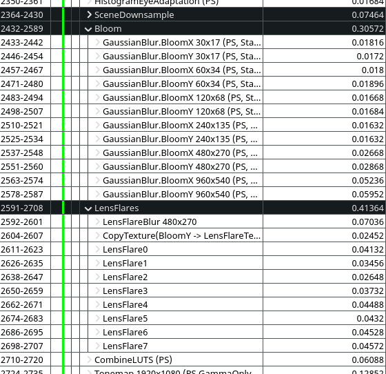
(Default UE4 bloom and lens-flares, around 0.794ms total)
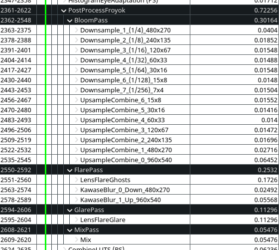
(New custom bloom and lens-flares (v2), around 0.723ms)
As you can see we are pretty close to the original render time of the engine for an end-effect that is much better in quality and look ! I'm pretty sure this can be lowered down further by using compute shader. UE4 original downsampling is only 0.075ms for example with just 5 levels.
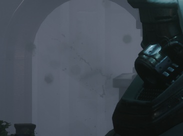
Note: the second version of my lens-flares combine several effects into a single pass, which is why some things like the halo are not mentioned anymore on the image above but are still present in the final render:
(You can compare this result against the old effect.)
Some quick bonuses in case there are still questions remaining.
Obviously, if you followed everything I did, then a Bloom intensity of 1.0 in a PostProcess volume will lead to a blurry screen because of the linear interpolation.
I don't recommend going higher than 0.3, but you can try 0.5 for extreme cases. Still, a very blurry screen could even be useful for gameplay purpose (like simulating blurred vision/damages).
So if you need a very wide bloom I recommend instead to increase the intensity of the emissive lights/surfaces on the content side. Now that the light is not added anymore, they take more time before saturating toward the whites.
Also if you are using a dirt mask texture, make sure its intensity doesn't go beyond 1.0 (unless it's a very dark texture of course). A very "bright" dirt mask will appear even in low light areas because of the way it is now combined in the tonemapping pass:
If you wish to optimize the lens-flare I presented in my previous article, here are some hints on replicating what I did:
Here is the list of documents that helped writing this article:
Additional publications and references:
Borrowed images: