Custom Lens-Flare Post-Process in Unreal Engine
Reworking and improving the native post-process effect.
Reworking and improving the native post-process effect.
September 15, 2021
This article shows how to modify the default Unreal Engine lens-flare post-process, from code to shaders. I always wanted to change the default Unreal Engine 4 lens-flares because it never felt good in my opinion. It's a post-process effect that lacks control and looks rather bland.
The fact it is broken too doesn't help (because of a UI bug) which means anybody trying to use it in a project will have some difficulties getting any artistic control over it.

(Isn't it boring ?)
So when a few years ago I stumbled across other games that displayed different kind of flares I started to wonder if it was possible to modify/implement something different. It's only recently that I was able to figure out how, mostly thanks to some updates of the engine that simplified quite a bit its rendering process.
Be aware that the following article is a long technical deep dive and assumes anybody reading it is comfortable with general shaders and C++ programming.
This article was written based on Unreal Engine version 4.25. Some of the steps involve modifying the engine source code, which should be applicable to version 4.26, 4.27 and the UE5 first early access as well without any issues.
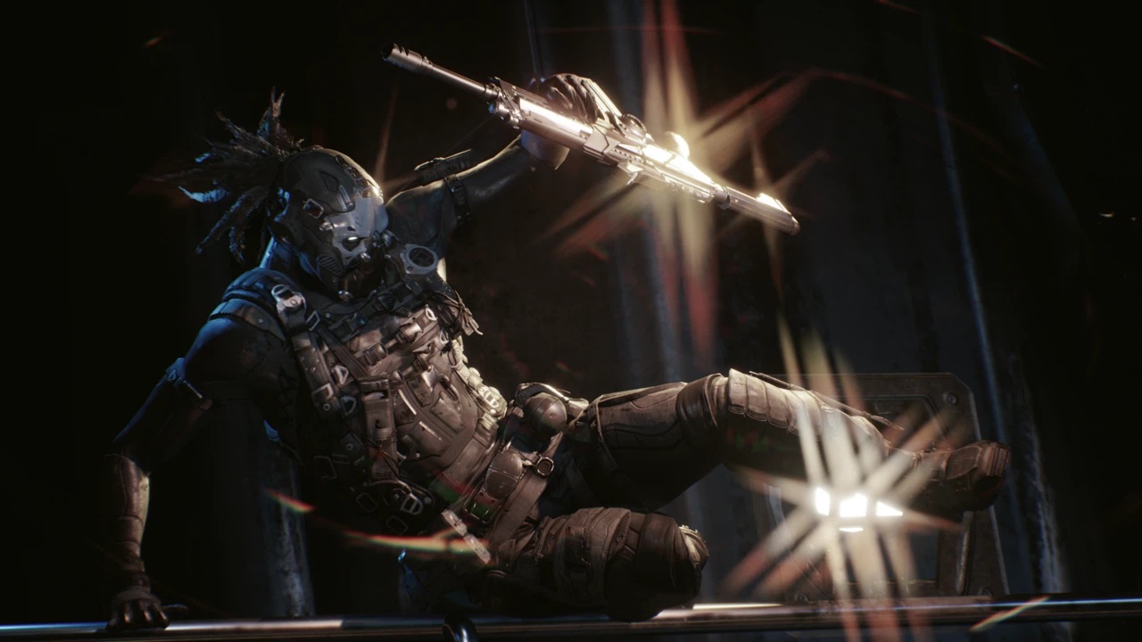
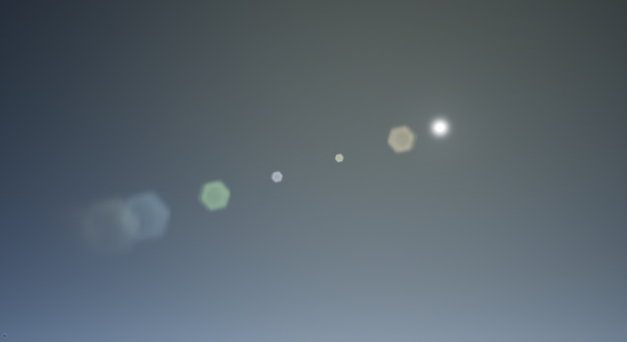
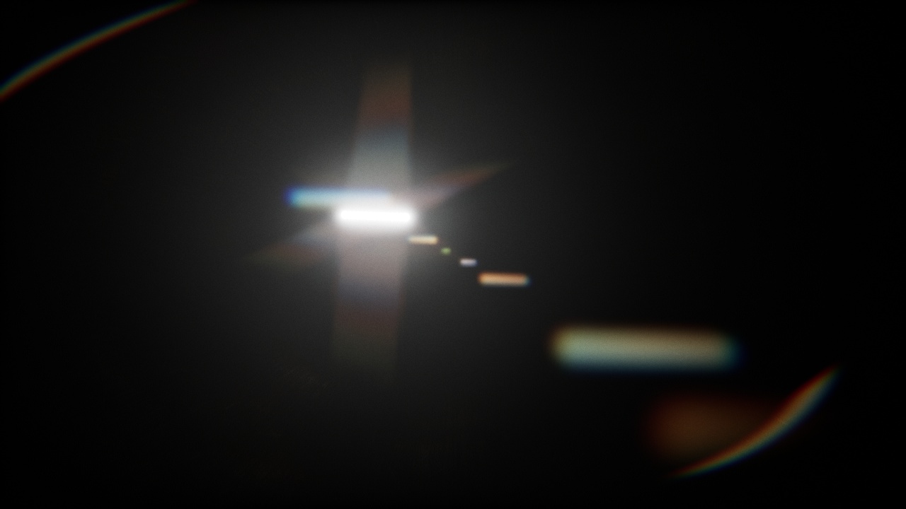
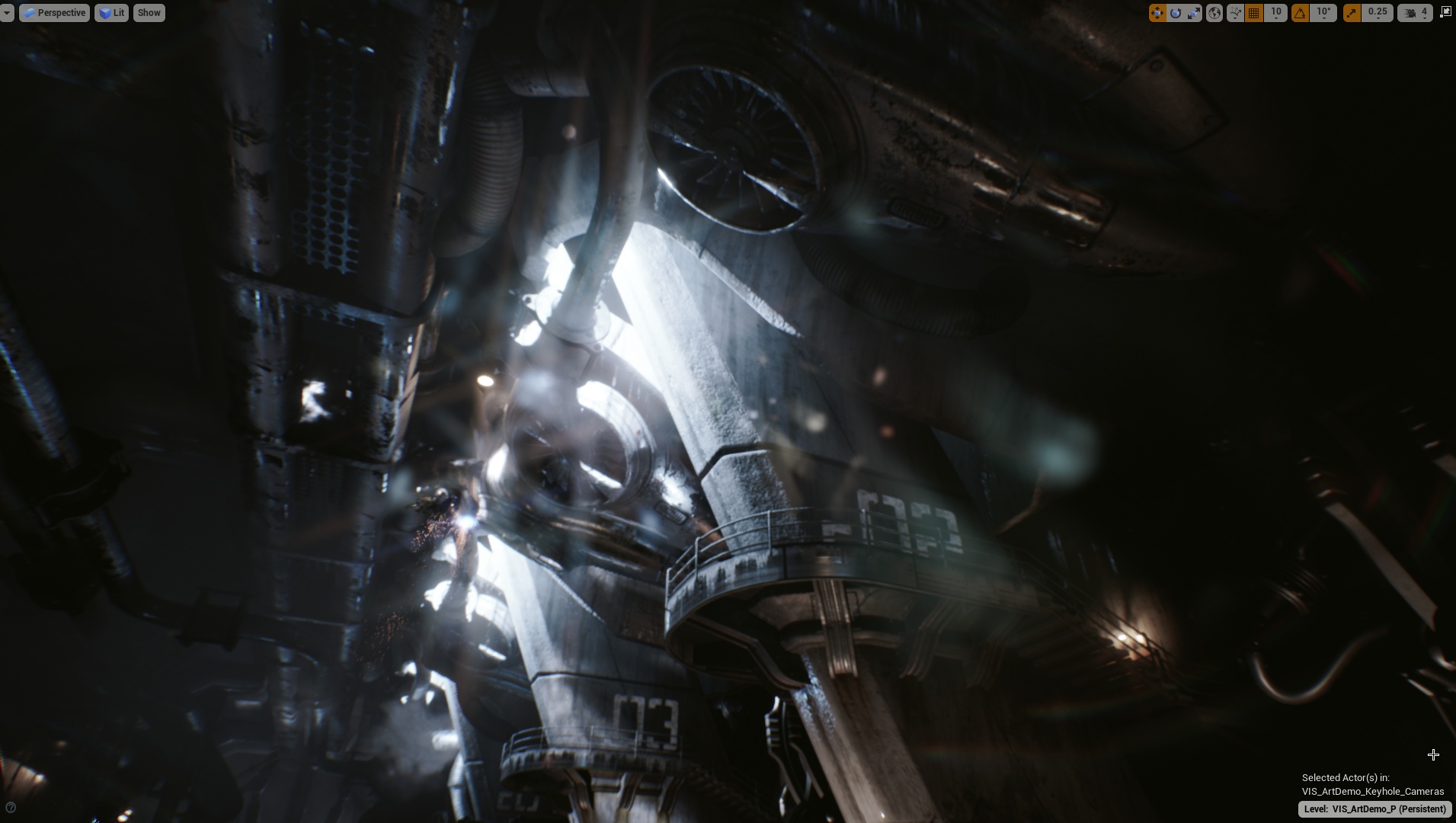
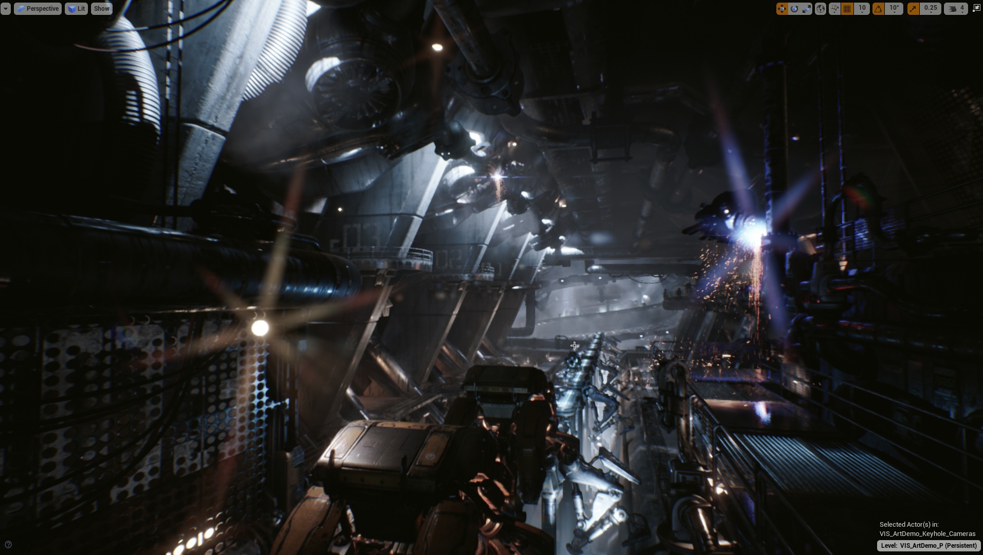
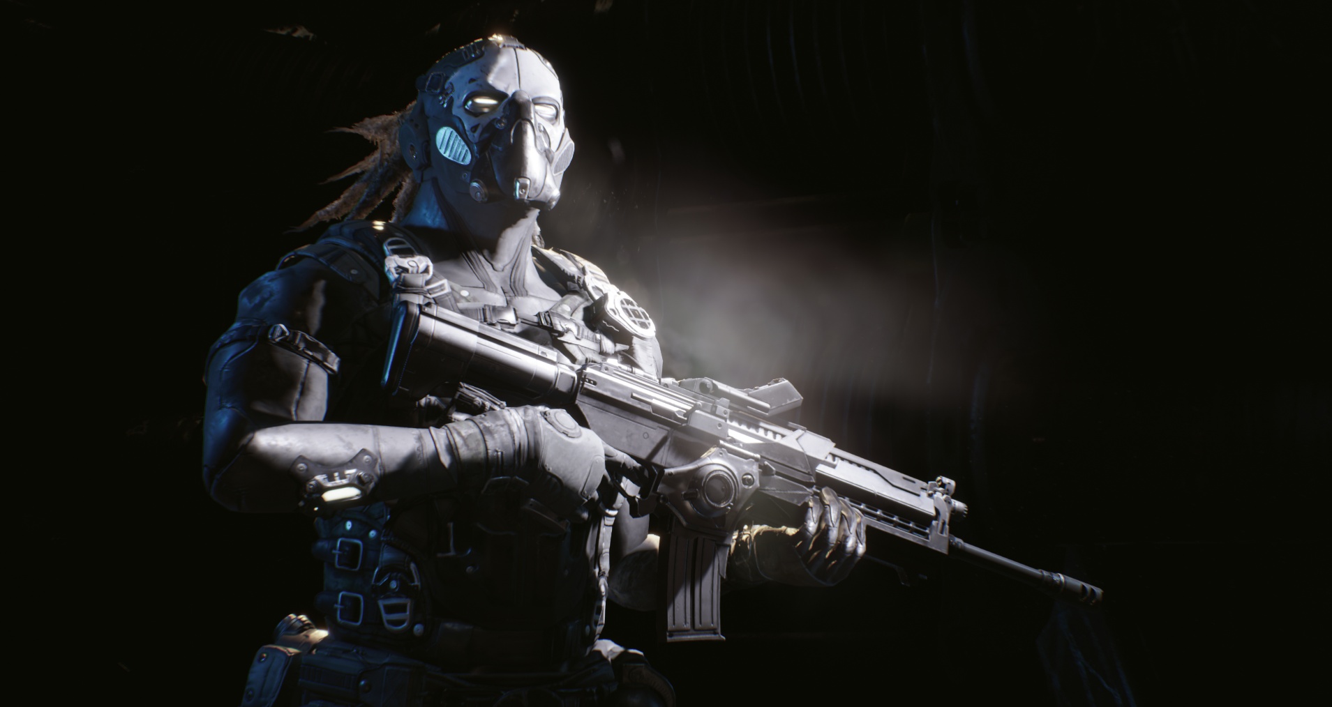
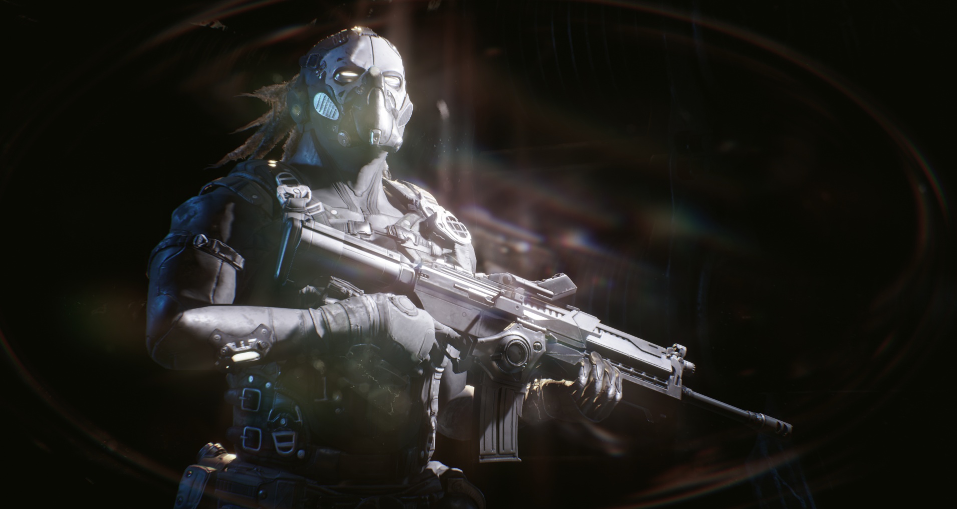
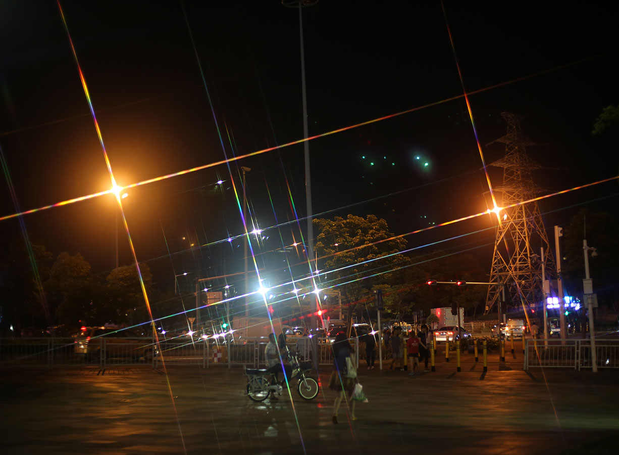
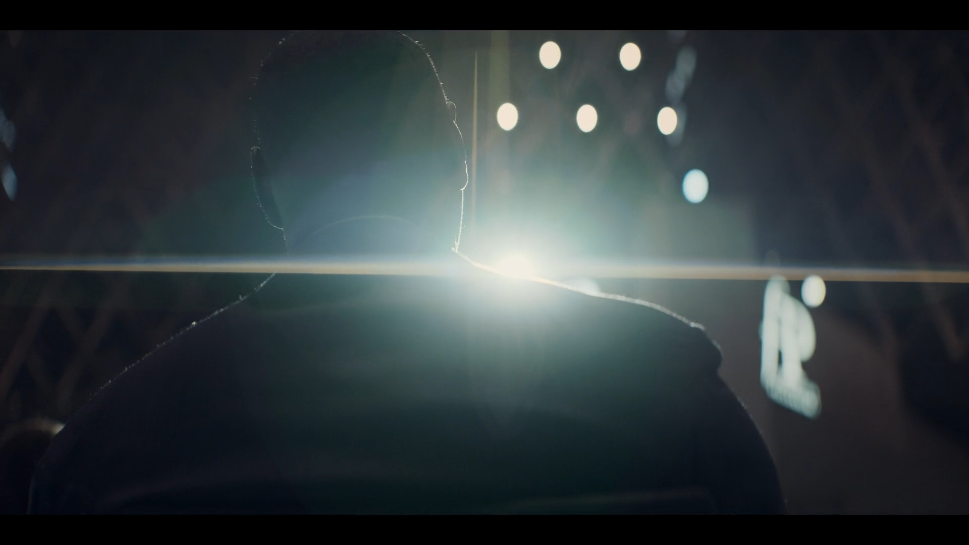
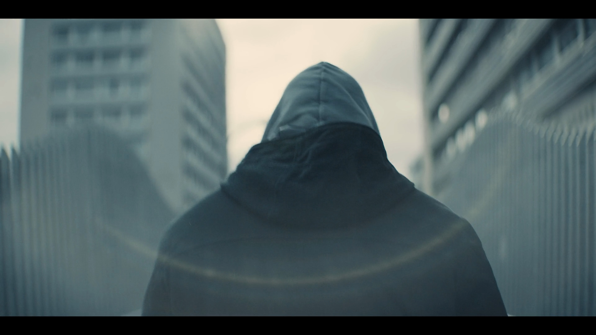
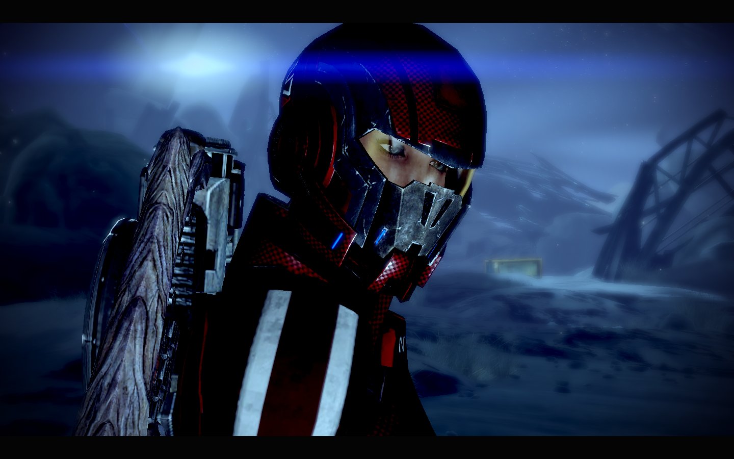
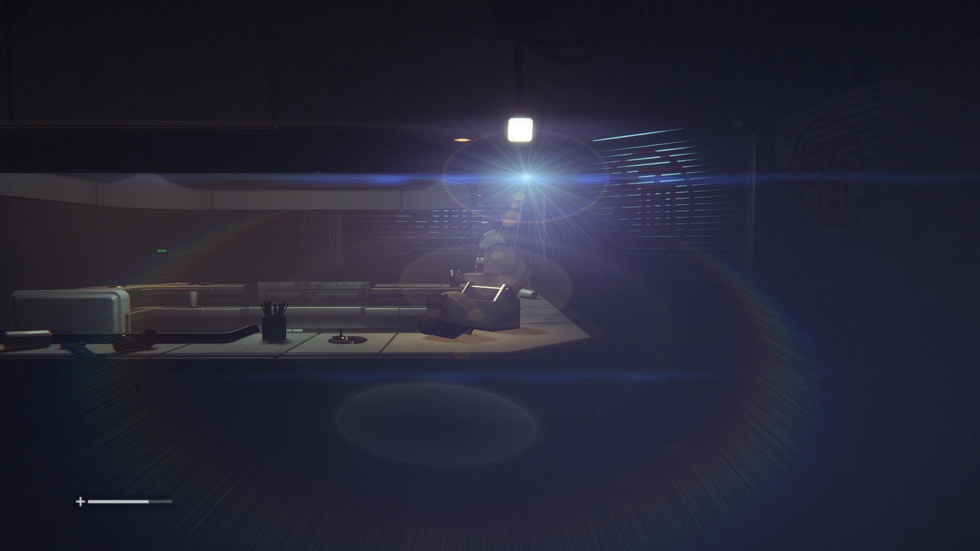
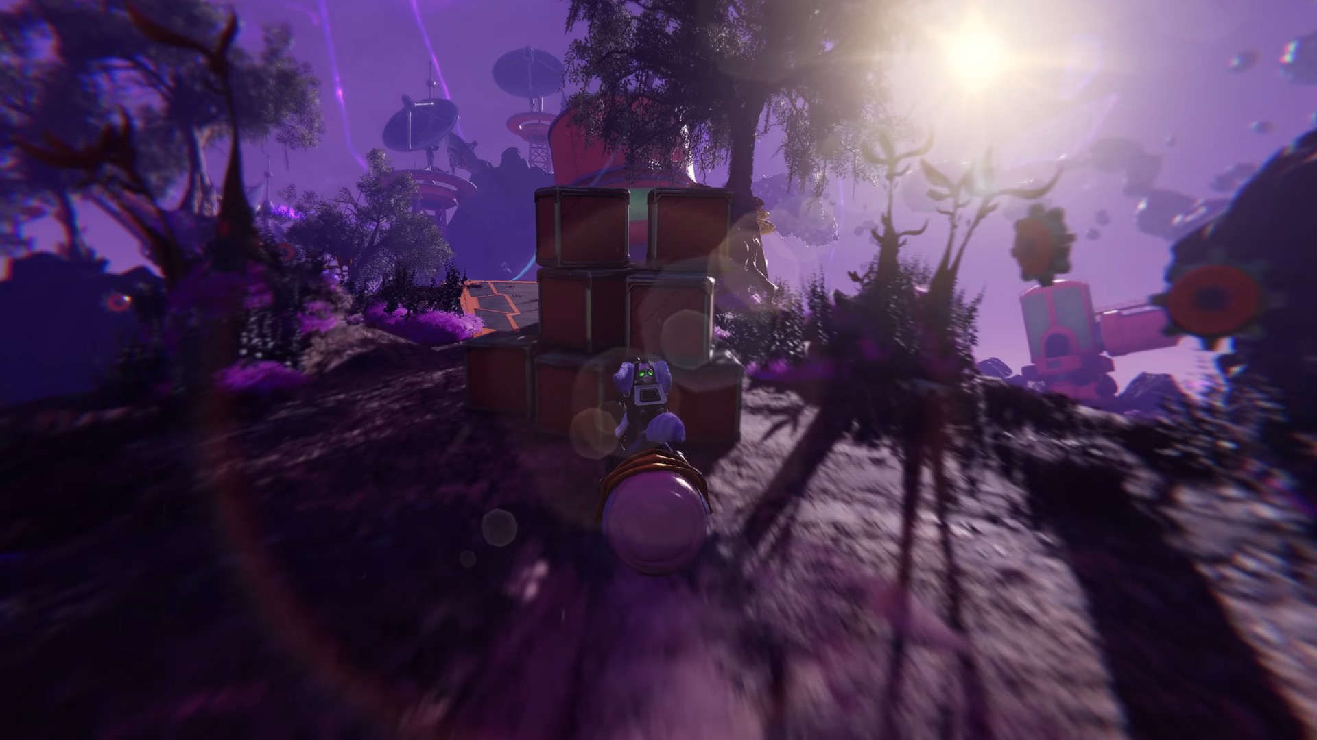
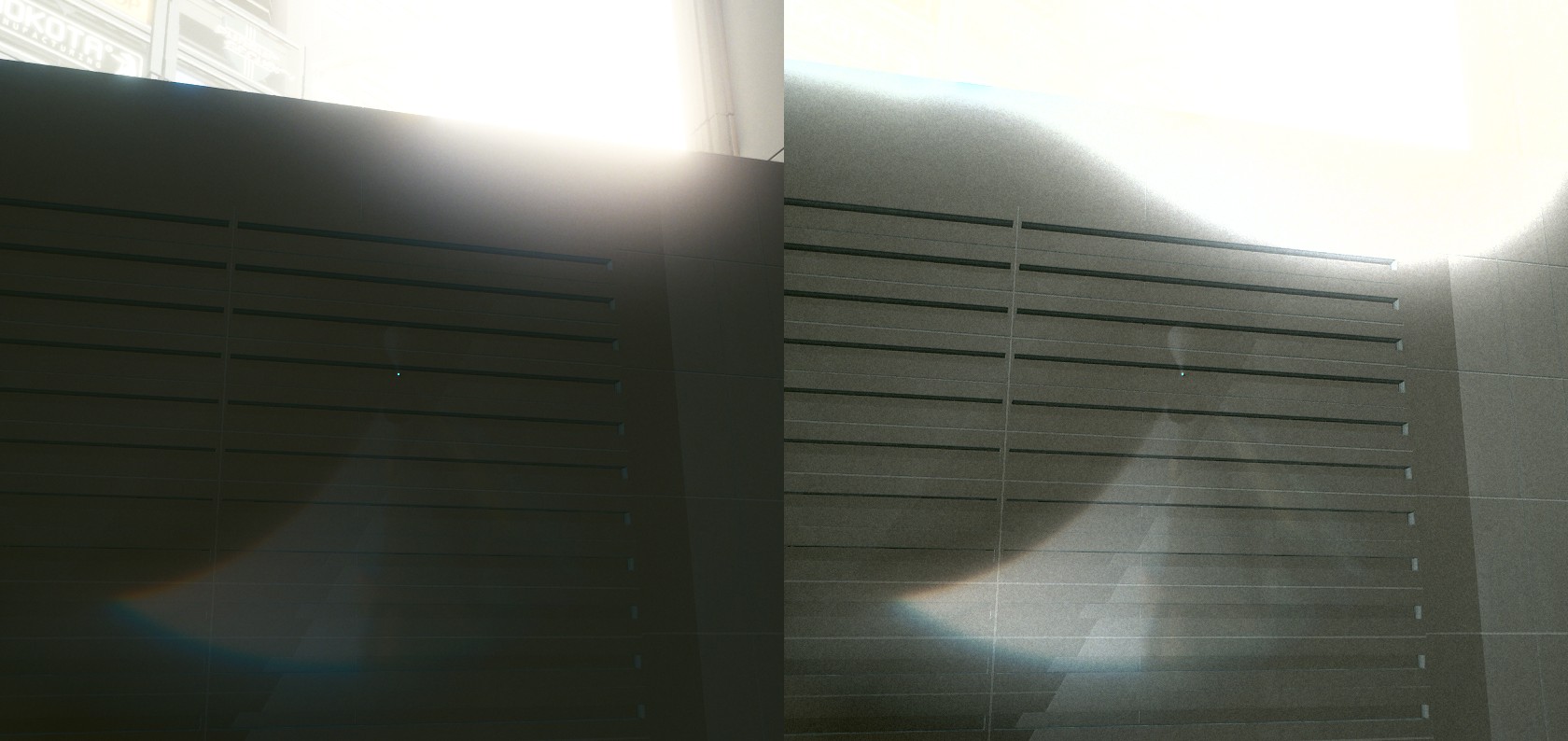
Before diving into details, I think it's important to look at what the end result looks like:
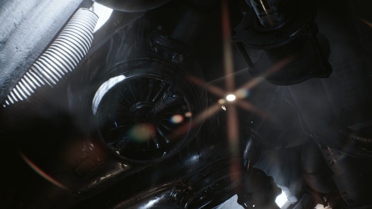
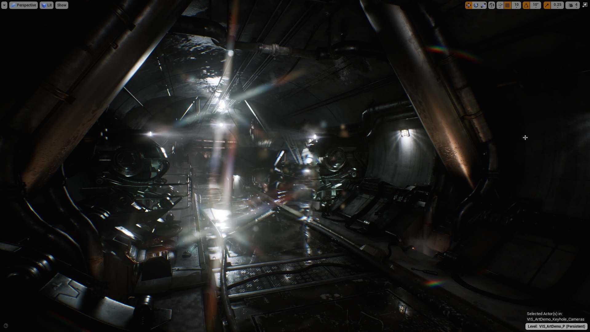
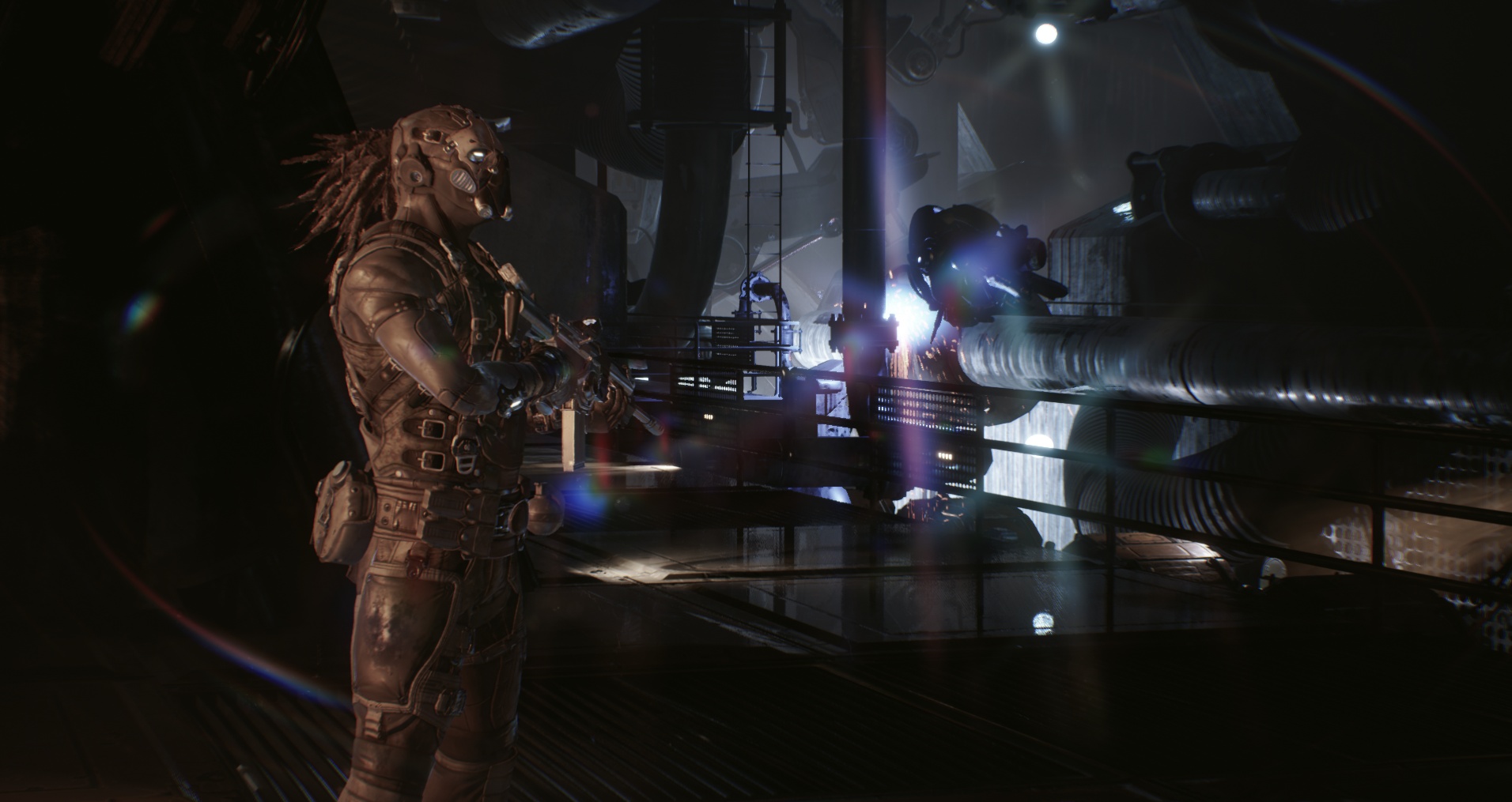
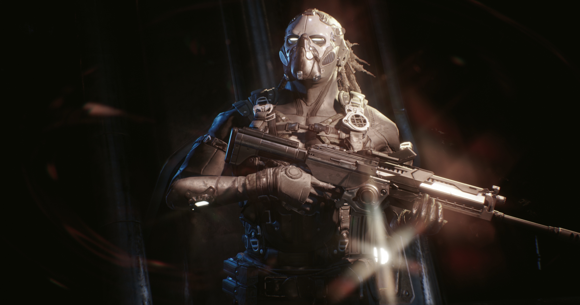
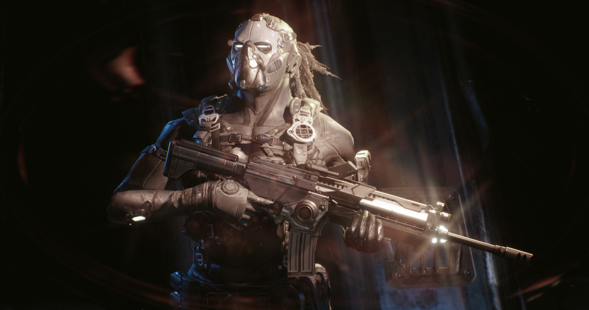
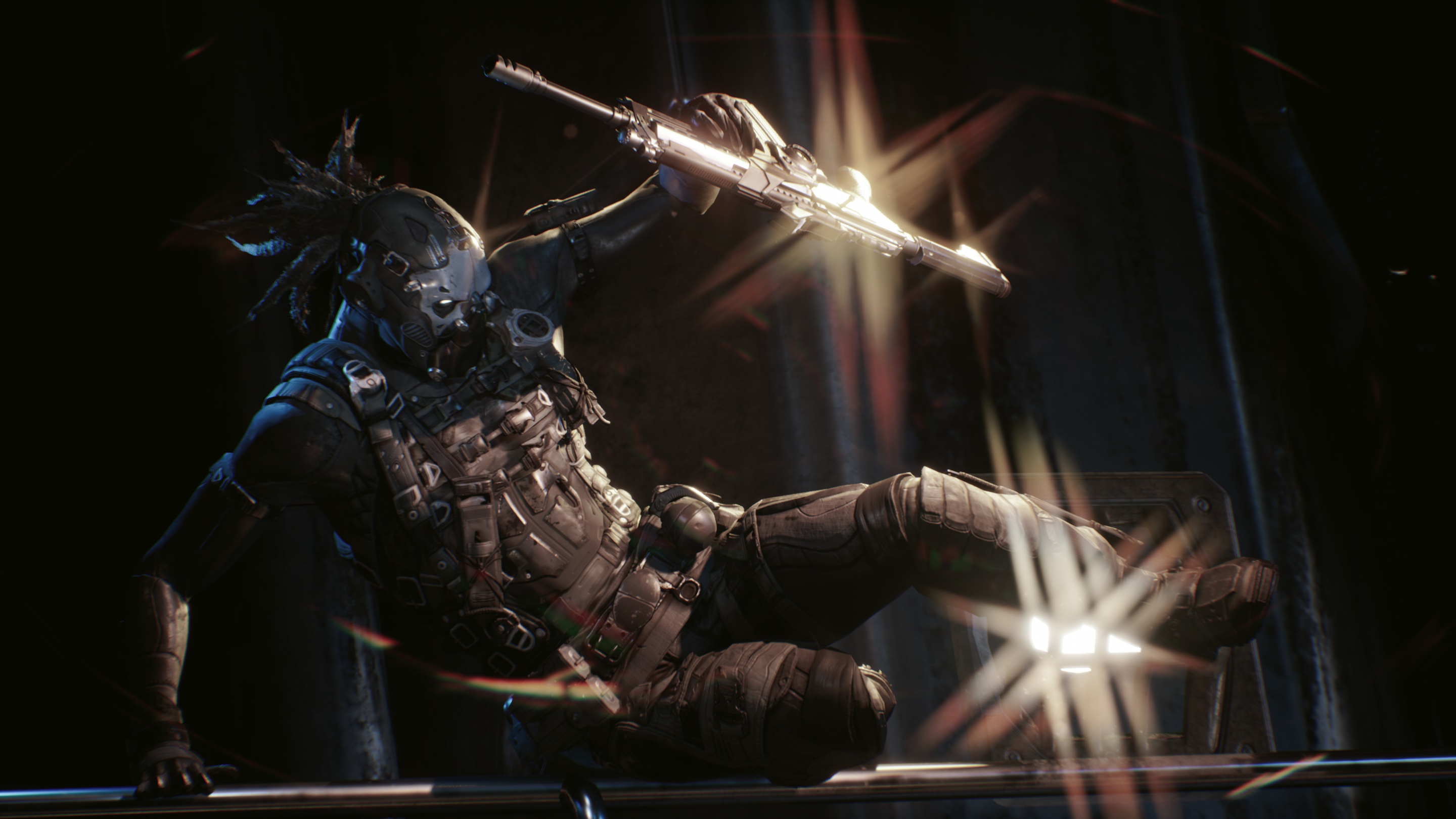
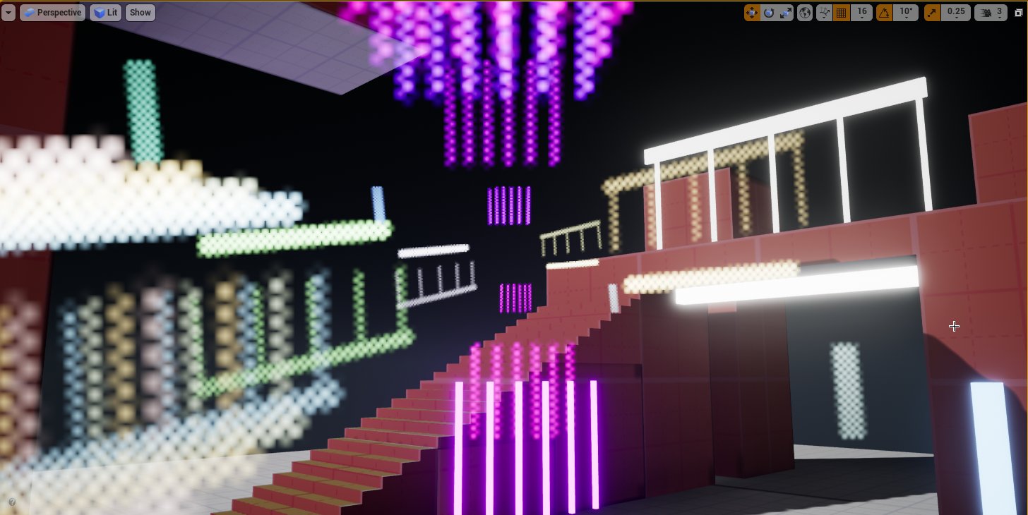
Here is it in context inside the Infiltrator Demo from Epic Games:
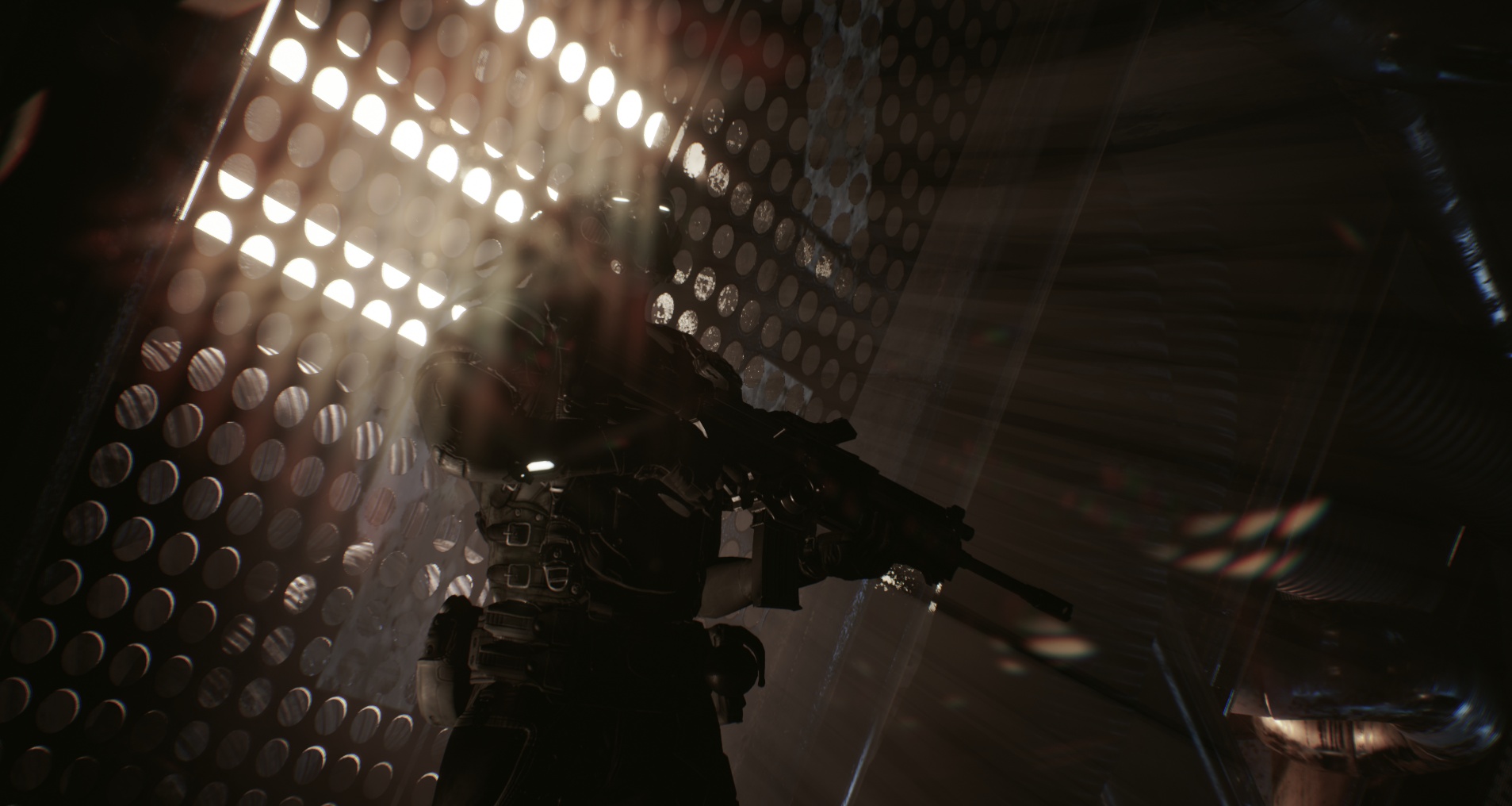
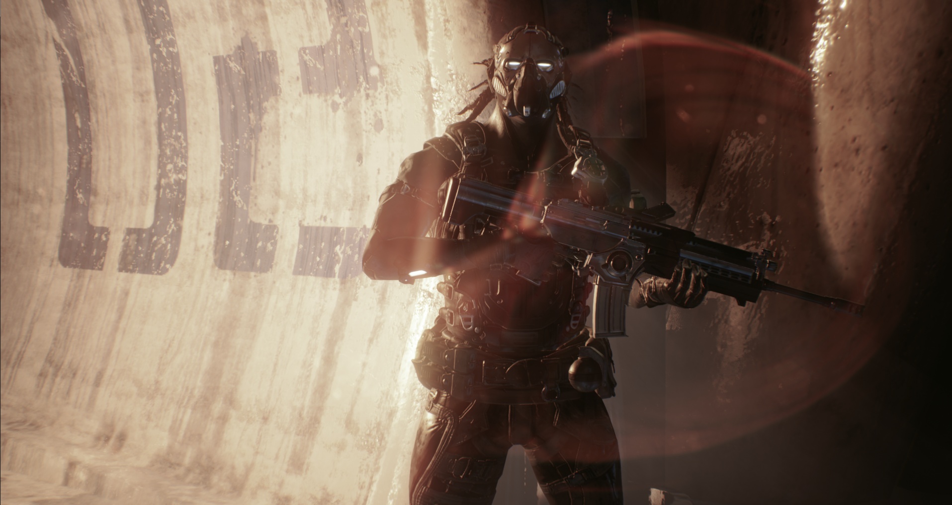
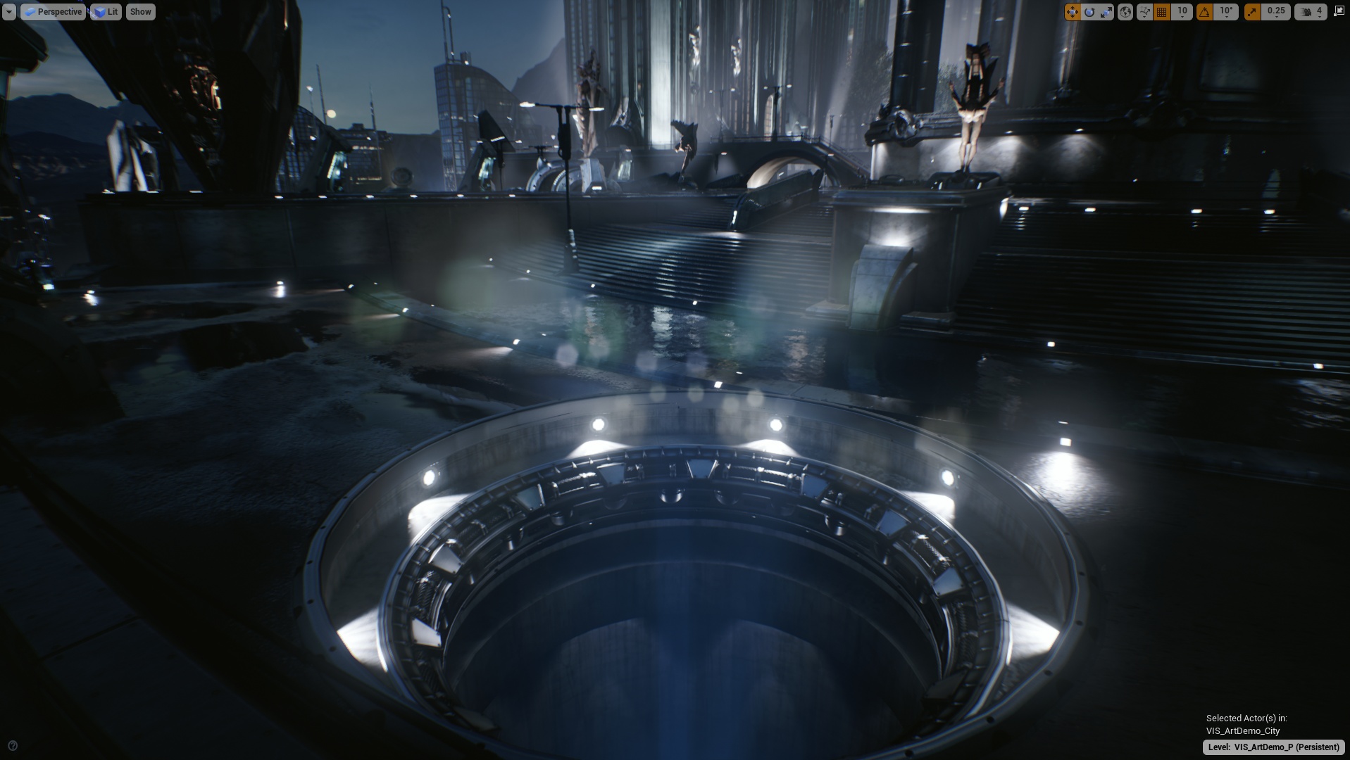
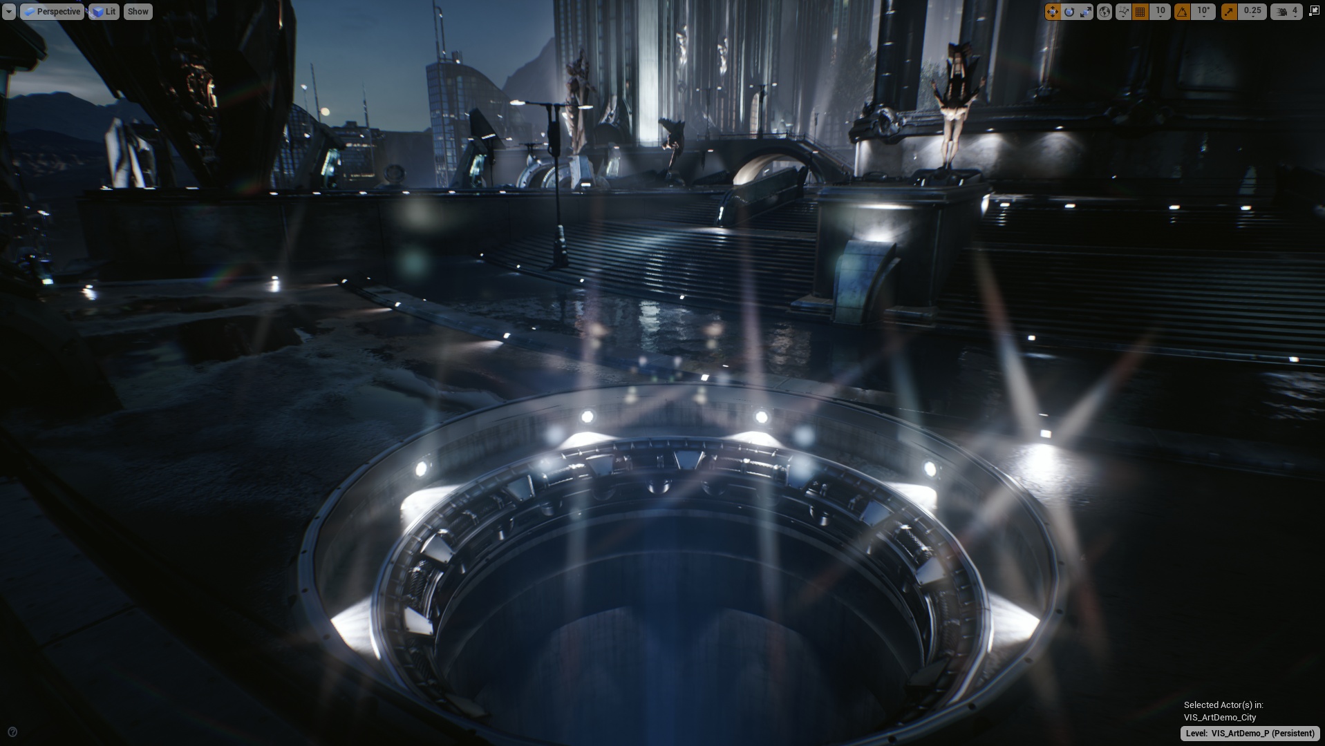
Below are comparisons between the original effect and the new one:
A lens-flare is a composition of several behaviors based on the way light bounces inside the lens of a camera. While initially seen as defects, which is why expensive lenses and even specific protections have been made to get rid of them, flares have become an artistic tool to add details on an image.
Similarly to Chromatic Aberration, it can be a used by artists to shape and enhance the look and framing of a subject. In the domain of computer graphics they can help achieve the feeling of a more realistic image.
Modern lenses are actually a composite of multiple glasses with different shapes that bend the light rays toward the sensor (which registers/captures the colors).
Because of this complexity, a light ray can scatter when refracted by a glass which leads to visual artifacts. When a refracted ray bounce inside the lens it can scatter again and bounce further until at some point it may hit the sensor but this time it is unfocused (contrary to a direct ray).
This is why multiple shapes can appear on an image from a single light source and create the famous "lens-flare". The coloration also comes from the way some glasses refract rays that have different frequencies, leading sometimes to only certain wavelengths hitting the sensor.
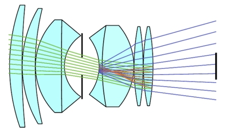
(Side view of a lens, with the diaphragm in the middle and the captor on the far right.)
I recommend taking a look at Wikipedia if you want to learn more on this subject.
Lens-flares exist in many shapes, which all depends on the way a lens has been built/designed but also on how the light enter the lens (straight, sideways, etc). Lenses from different constructors won't lead to the same visual results.
There are three main categories of effect that can constitute a lens-flare:
It is also interesting to note that the lens-flare look can change when the lens is dirty. For example water droplets can bend the light rays before they enter the lens.
(Even with our own eyes we can see glare on lights because of our eyelashes)
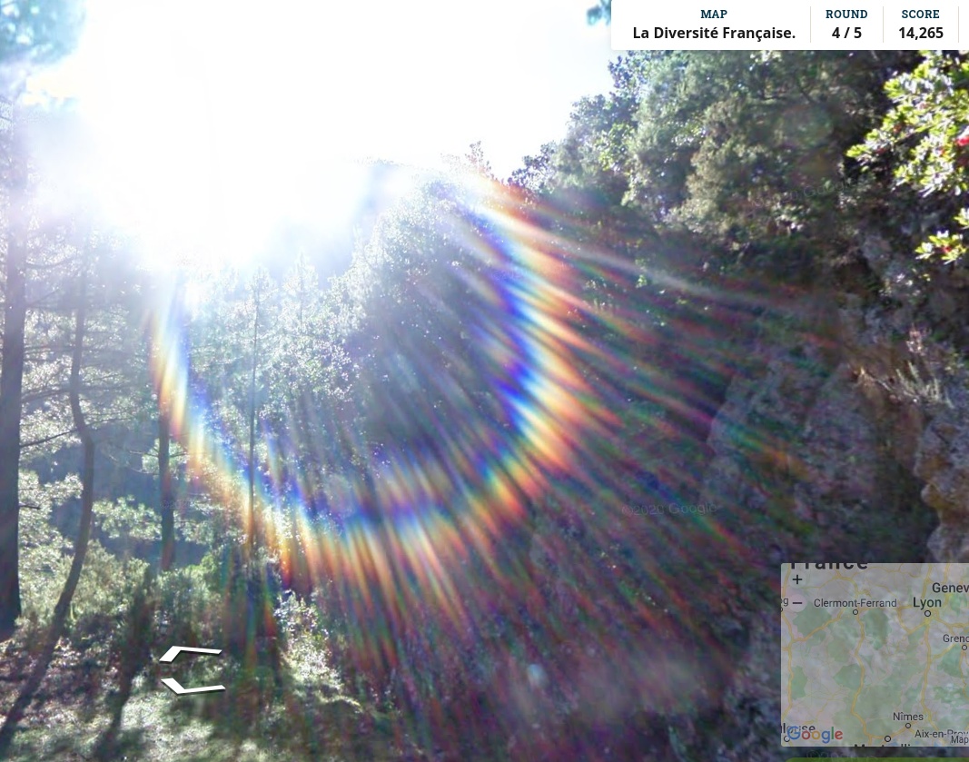
Finding good references is not always easy, especially on the Internet as most of time lens-flares are faked in post-production into content.
The examples below were made by my colleague Nicolas with a few different lenses:
(Lens Sigma, 30mm, f1.4)
(Lens Tokina, 11mm, f2.8)
(Lens Canon, 85mm, f1.8)
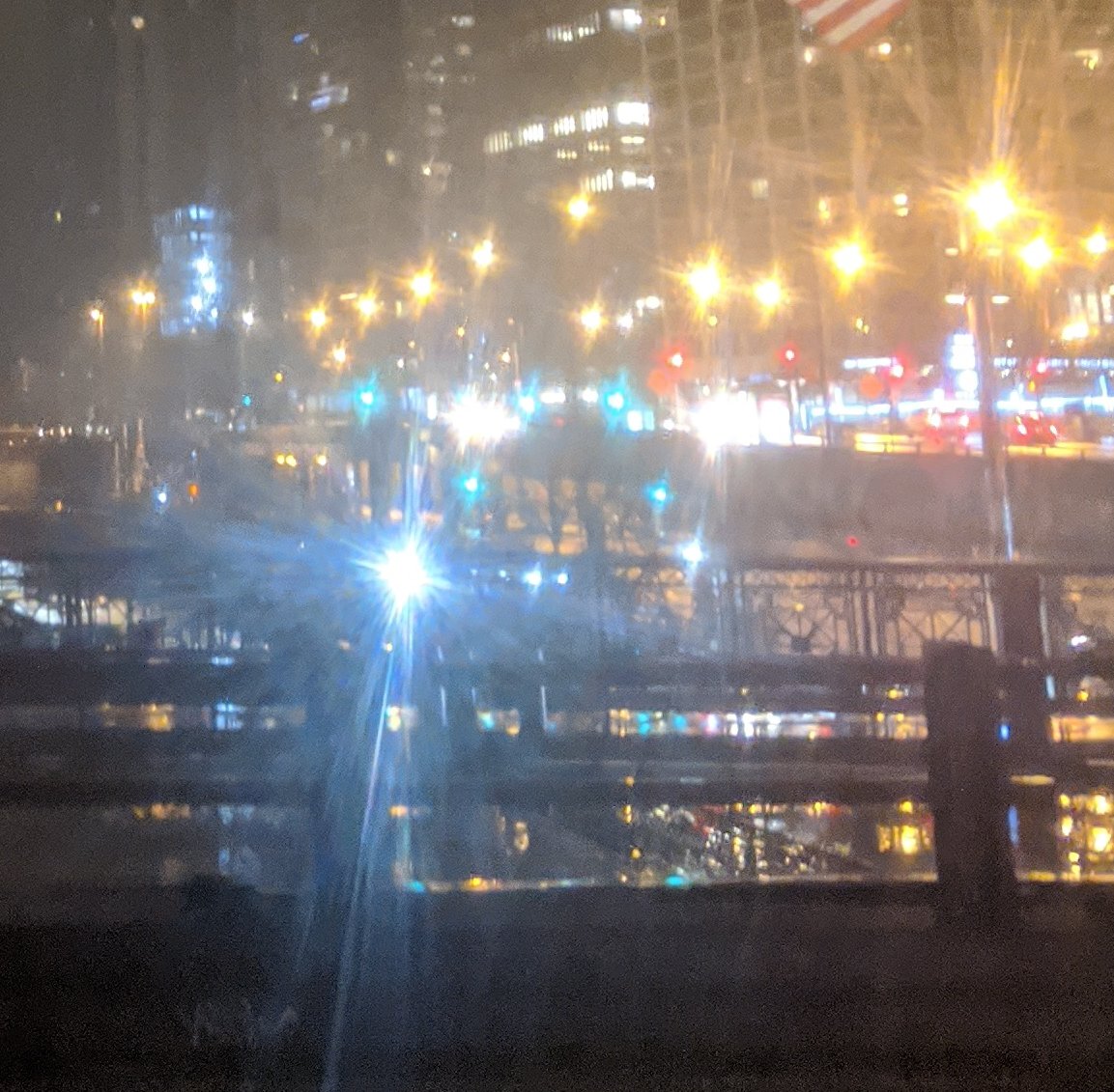
Other examples found on Internet:
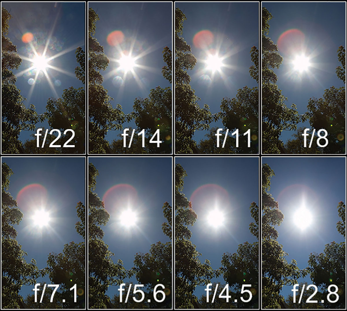
(Effect of the aperture on the size and shape of the effect.)


Some lens filters can even exacerbate some part of the lens-flares. For example star-light filters can create long lines on light sources (the number of branches depending on the configuration of the filter):
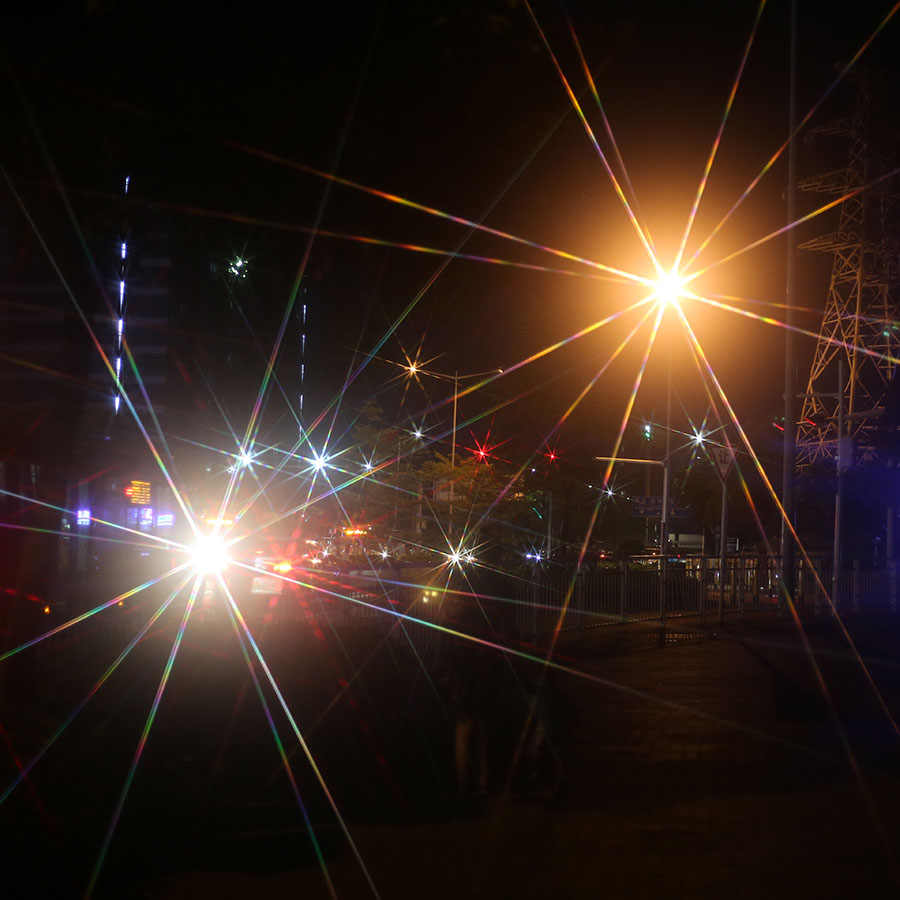
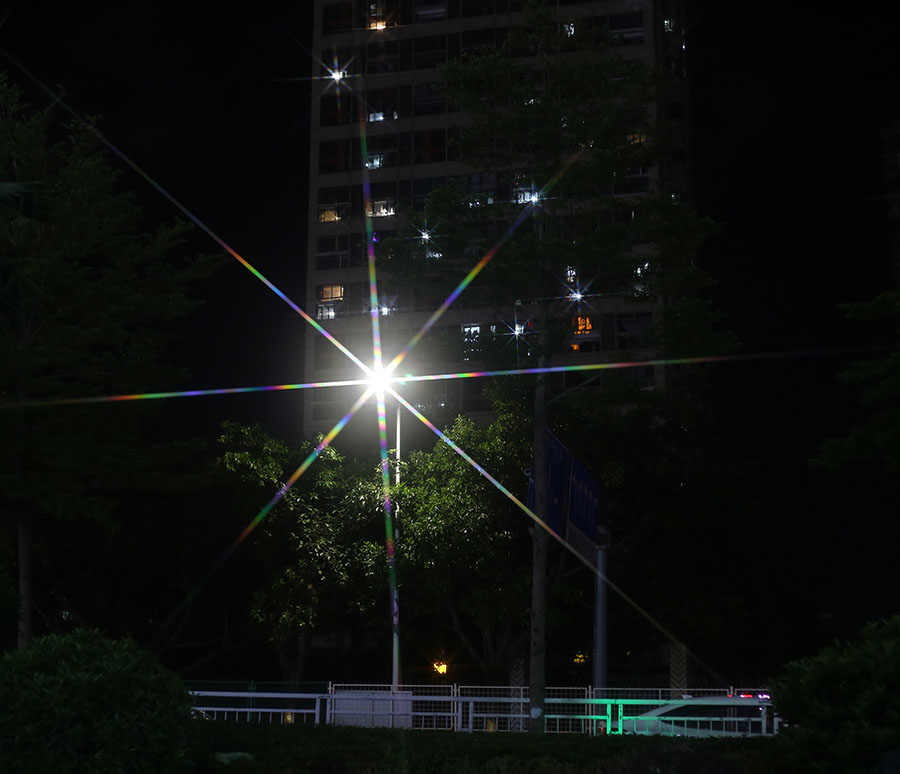
For more details on star filters and how they work you can take a look at this article.
Anamorphic lenses are a type of lenses that compress/stretch the image on one axis. It was initially used to fit more information on film. The counterpart is that any flare that may be captured will appear deformed when the image is put back to its normal ratio. More details in the dedicated Wikipedia article.
This is how J. J. Abrams created (and over-used) them in the movie Start Trek for example. Mr. Abrams deliberately shot flashlights at the camera to make sure glares and flares would appear on the image. In the Star Trek movie released in 2009 you can see the round shapes of the flares being squished:


I also wanted to mention Lupin, the Netflix show released in 2021, which features some really nice looking flares that I haven't seen elsewhere before:


It seems they are produced with a technique called "ring of fire" which is about putting a metallic cylinder in front of the lens to get additional light bounces creating this specific type of granular and colored rings. Lupin was filmed with Anamorphic Lenses too which create these non regular rounded shapes as well.
So real lens-flares are nice, but they are not easy to replicate as simulating lenses and light rays that go through them can be quite complex. So in real-time applications, especially video games, different methods have been used to achieve a cheaper but still effective result. There are three general categories:
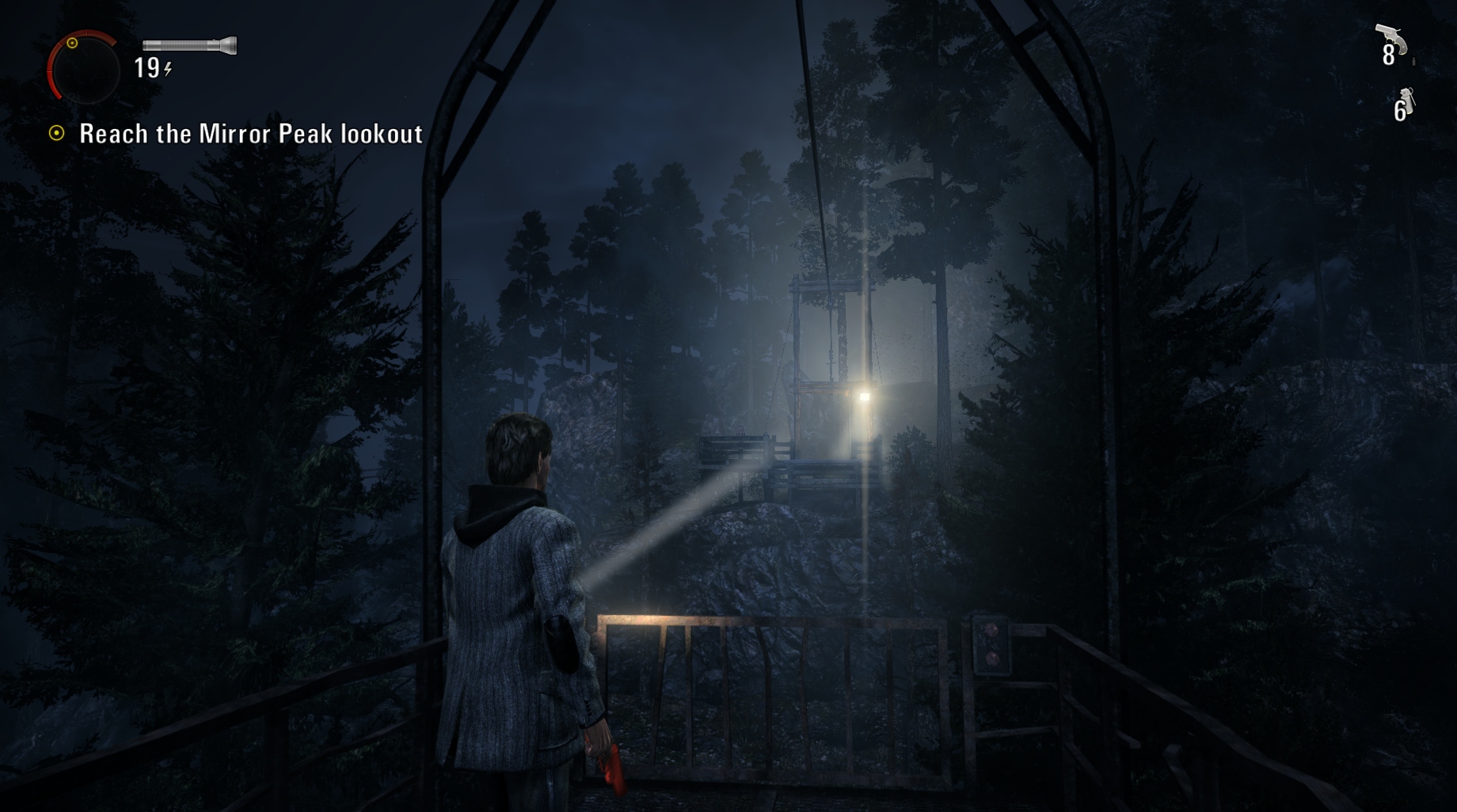
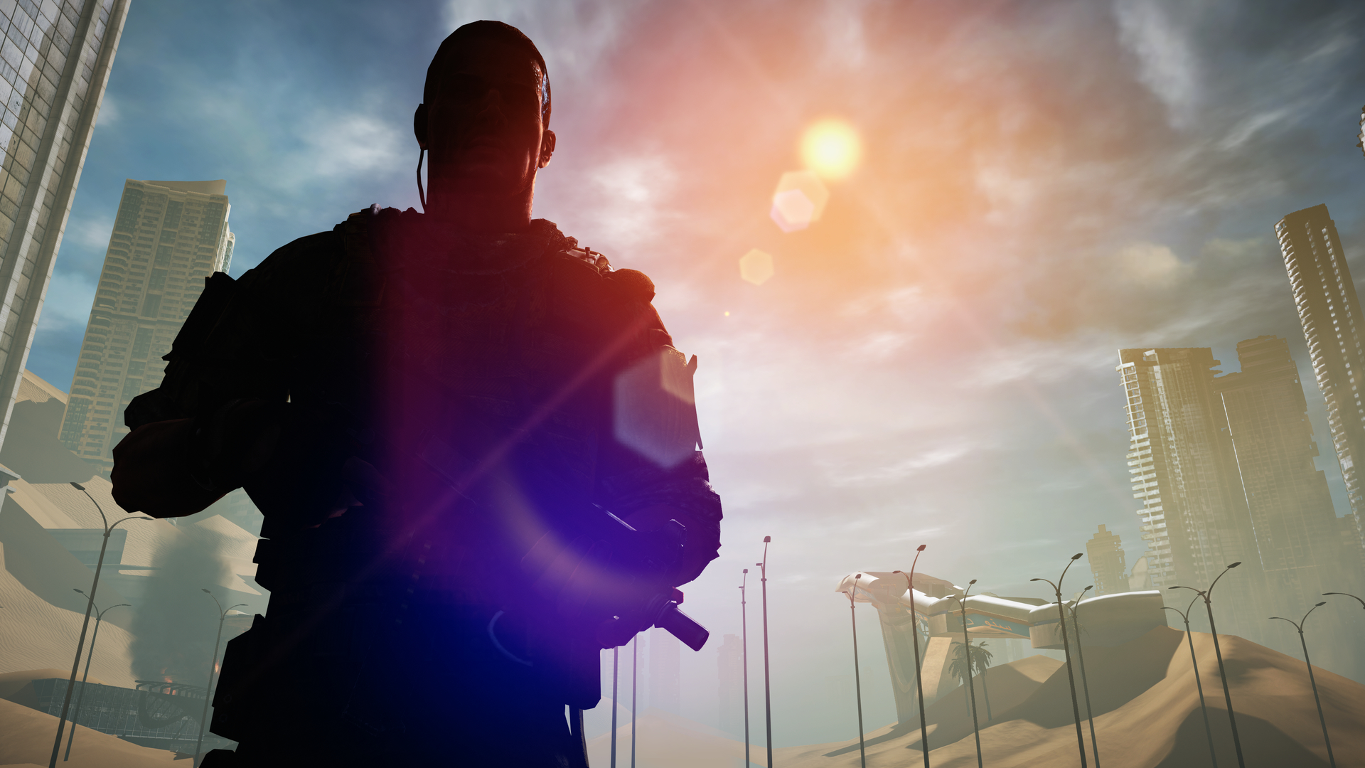
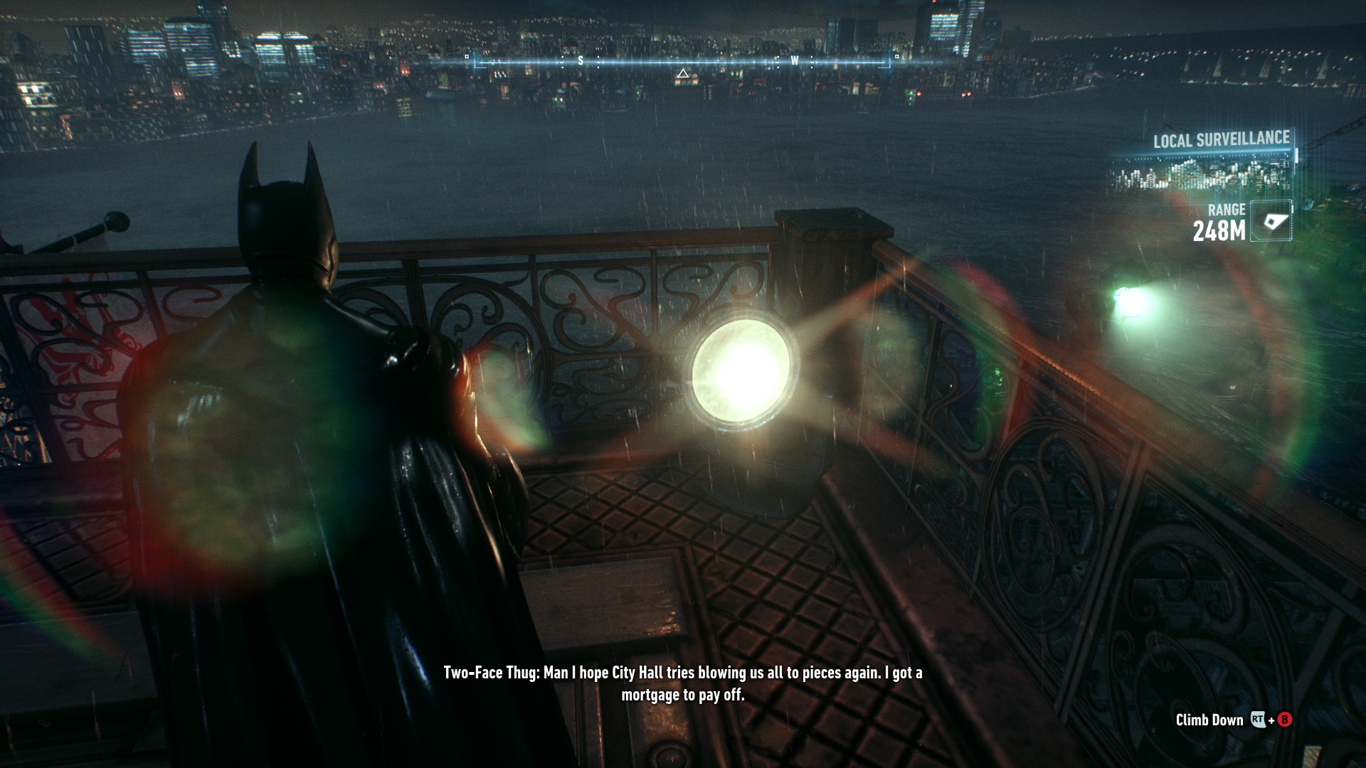
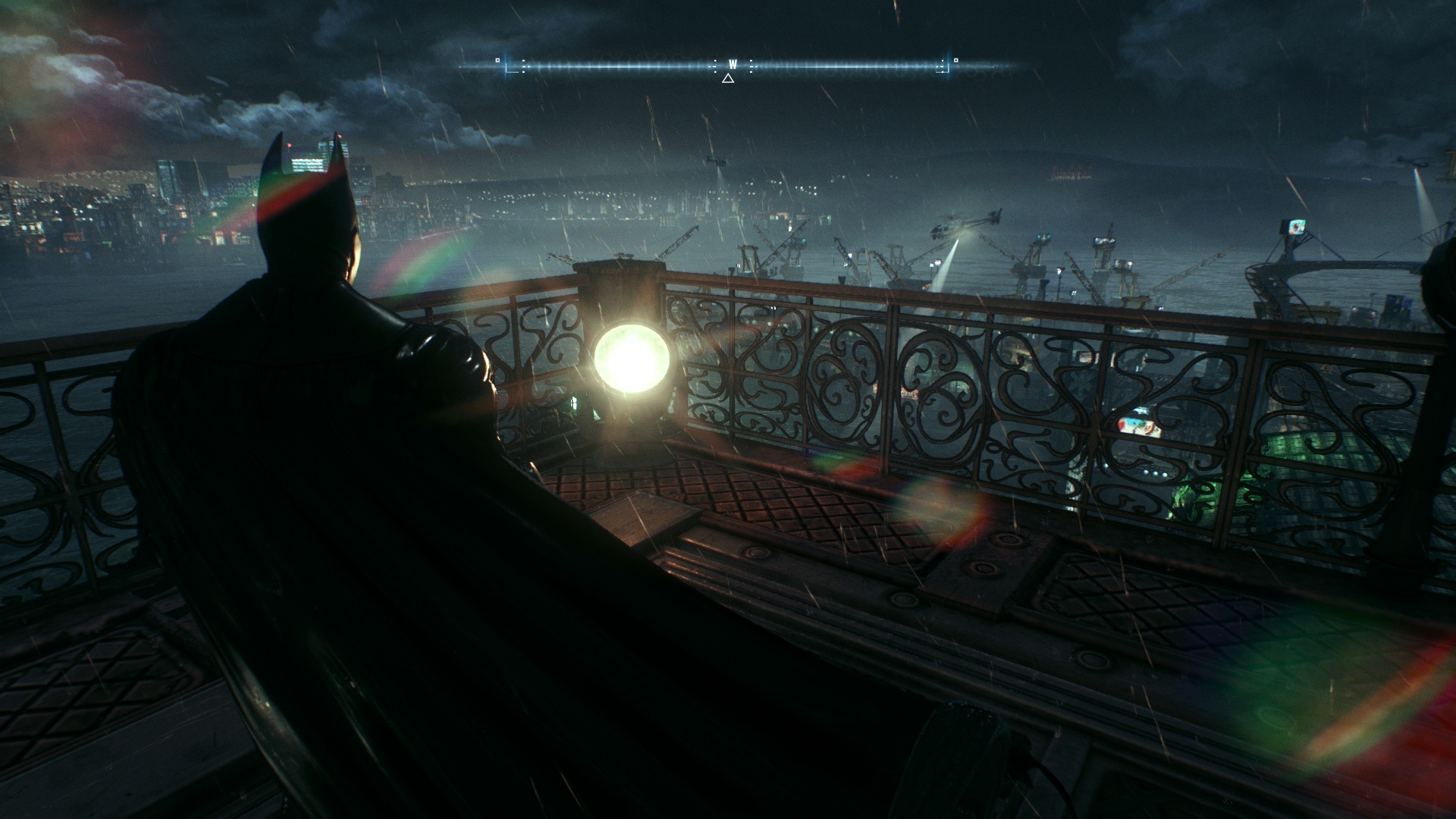
(Batman Arkham Knight, 2015)
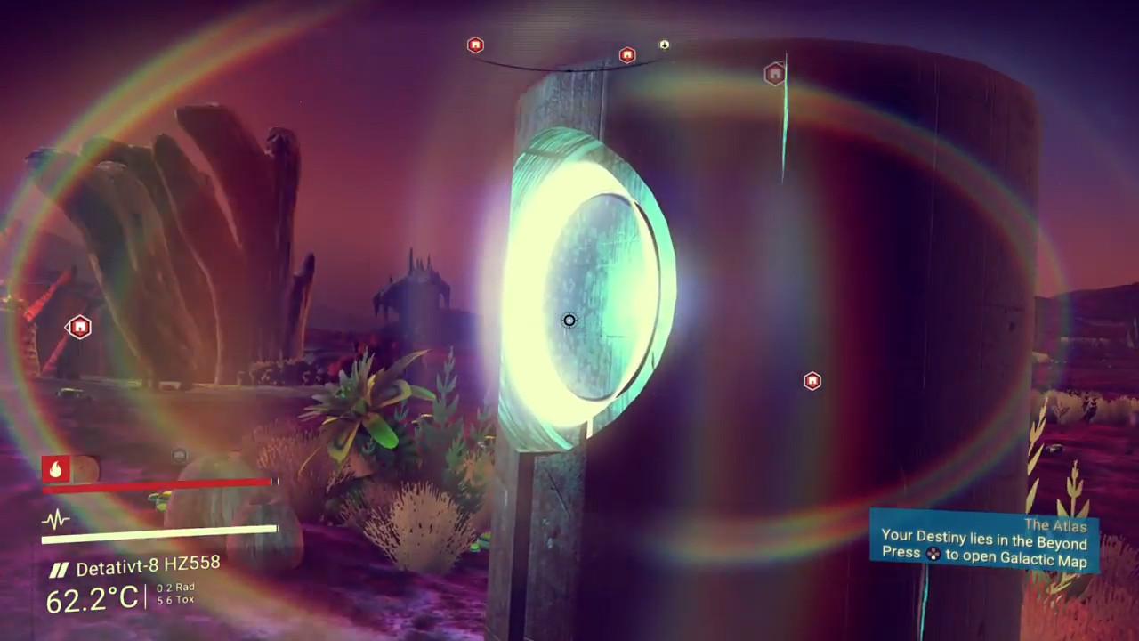
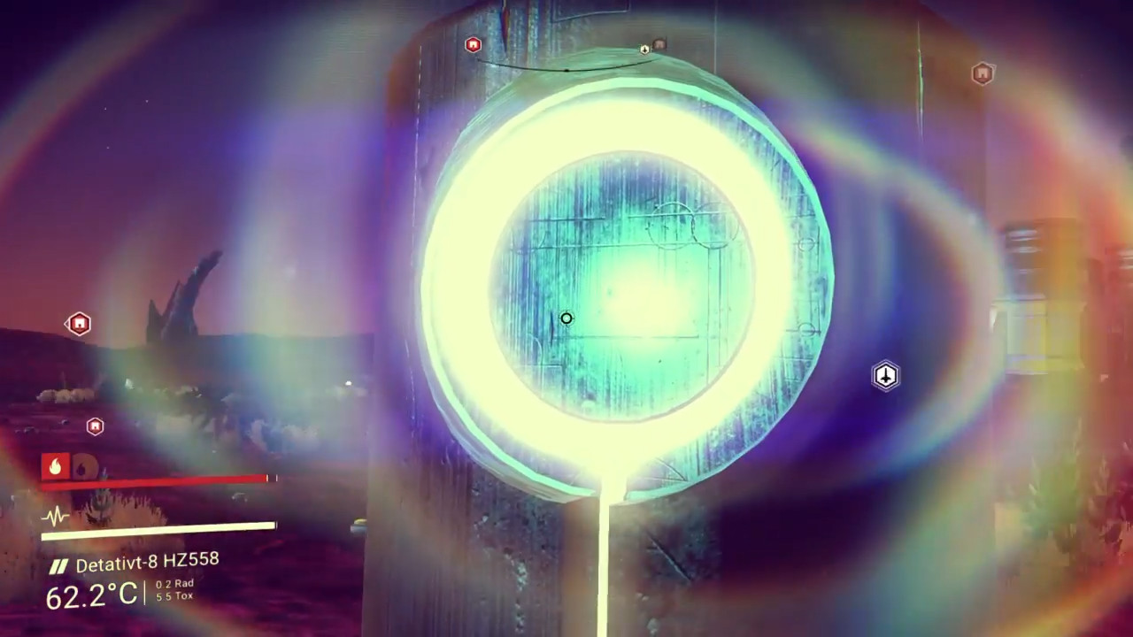
(No Man's Sky, 2016)
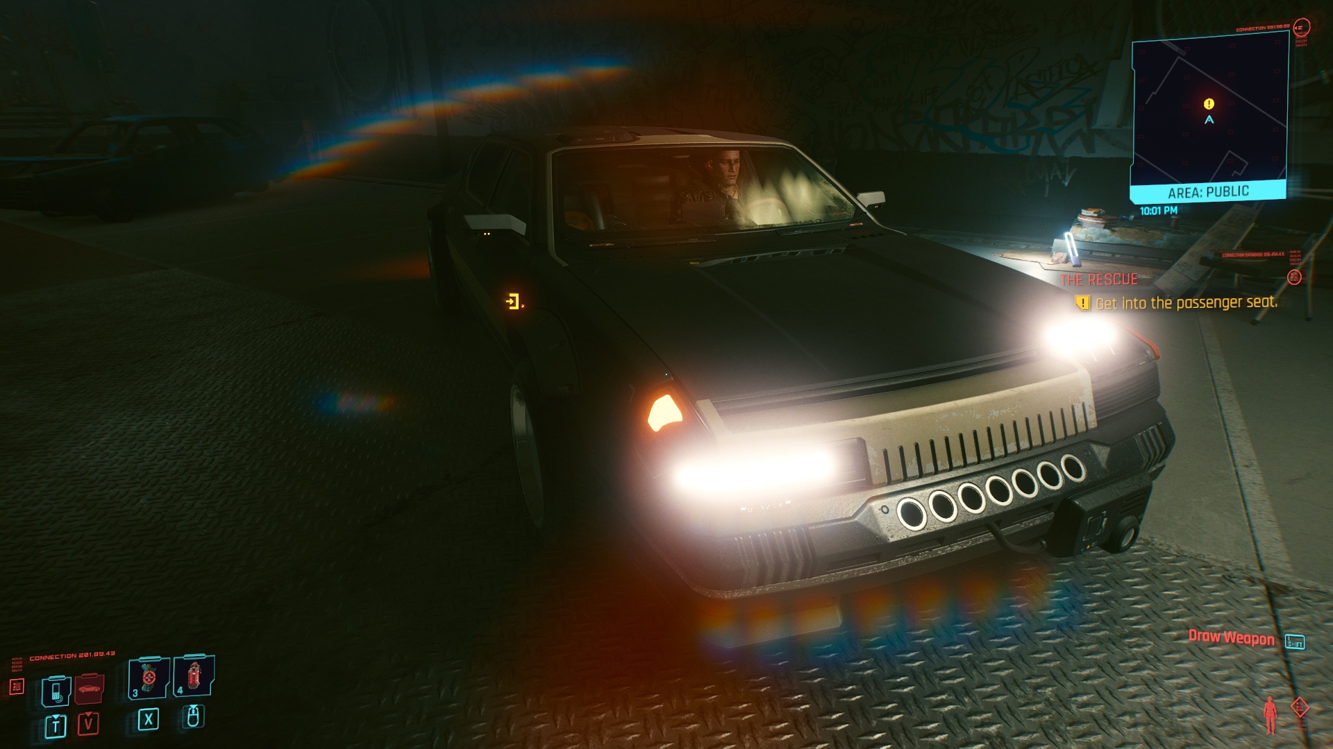
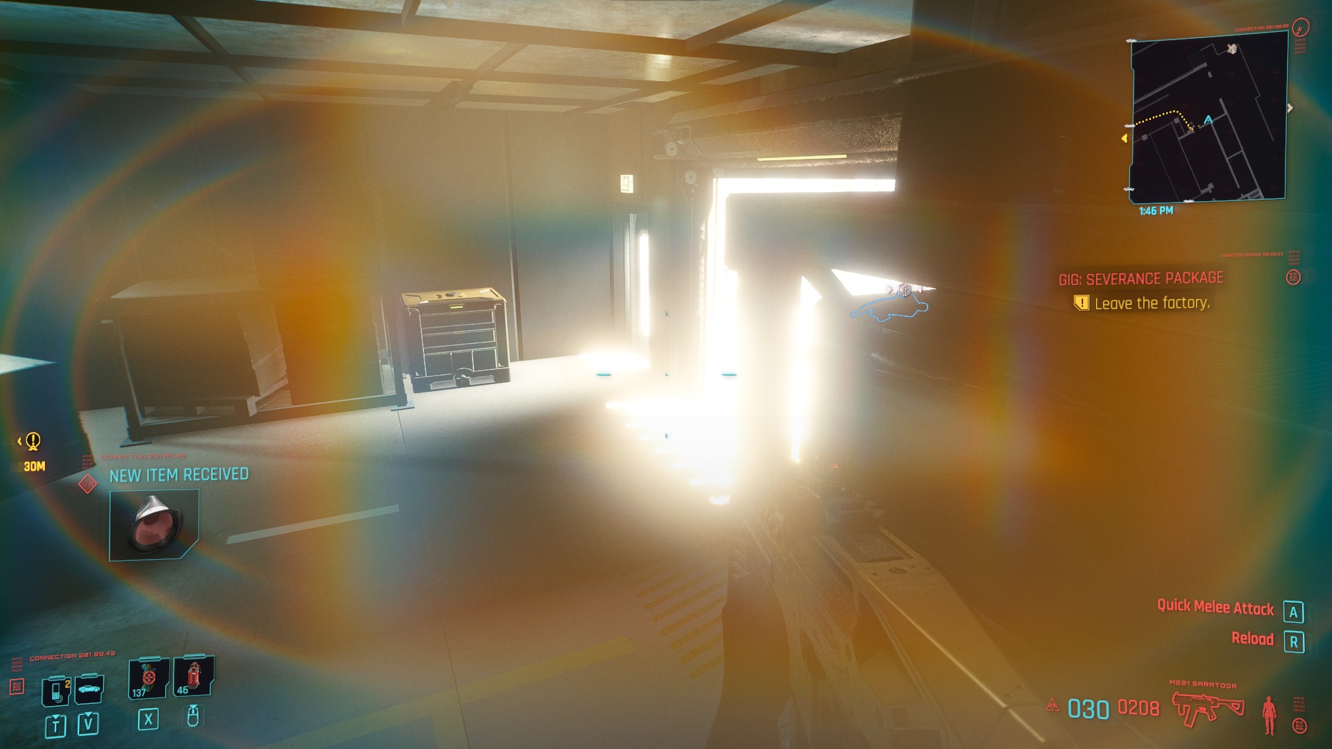
(Cyberpunk 2077, 2020)
Before diving into my own implementation, I wanted to look at some of the examples mentioned above in more details. They are using a few interesting tricks worth knowing about.
Every details I mention below are my own interpretations as I could only reverse engineer the behavior of the effect from playing the games and looking at how some things are rendered with graphic debuggers.
Cyberpunk 2077 post-process effect seems to be very similar to John Chapman's article in term of behavior, which is is quite straightforward to understand.
In the original implementation (see the article before going further), the effect is made by sampling the source buffer several times to create the ghosts while a radial distortion is used to create the halo around the edge of the screen. Then additional passes add chromatic aberration and blur everything together.
Cyberpunk does everything in one pass inside a buffer at 1/2 the game resolution. It re-uses the downsampled buffer of the bloom as a starting point and samples it several times to draw the ghosts (4 or 5 of them) and the halo, all in one go. This avoid the need to blur anything since the Bloom effect already did it. The chromatic aberration is done by doing 3 samples instead of one with a different directional offset from the center of the screen.
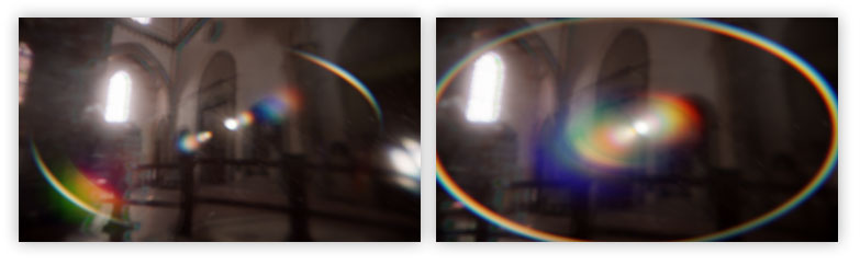
Cyberpunk doesn't use the radial mask contrary to the method it seems to be based on. This mask is normally used to hide the halo effect at the center of the screen. One of the reason to use this mask is to hide some artifacts produced by the UV distortion, which can be seen in the game (the flower petals around the dot):
(Normal in-game capture vs contrasted one)
Another interesting game I mentioned is Batman. The lens-flares in it are a bit different from what I have seen in other games.
Like in Cyberpunk, several ghosts are drawn in one go in a buffer (1/2 the game resolution as well) at several scales to create the light bleeding effect. Here as well it is done by retrieving one of the downsampled buffer of the Bloom generated before. Each ghost is sampled 3 times to create a Chromatic aberration effect. However it shifts the red and green component instead of the red and blue (my guess would be because the game is overall blue since it happens at night).
Ghost are not sampled as-is however, a radial distortion effect is applied at their center to make the effect rotate. So pivoting the camera make them turn when the content drawn is at the center of the screen:
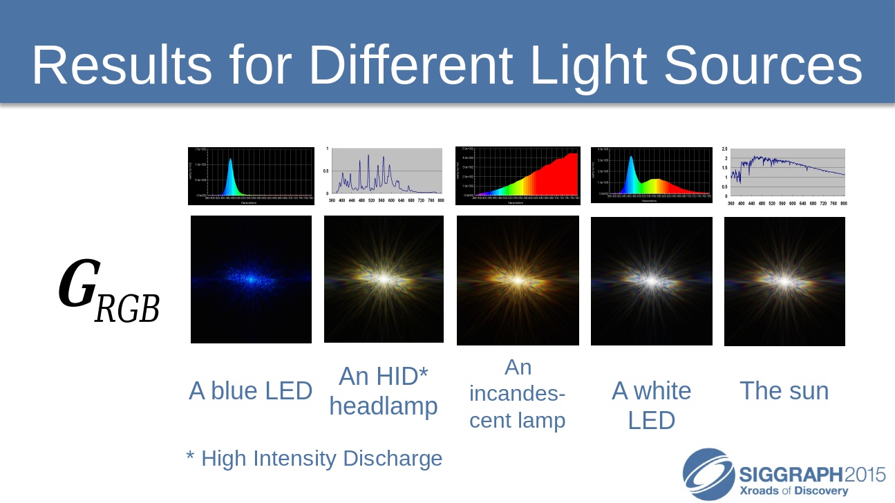
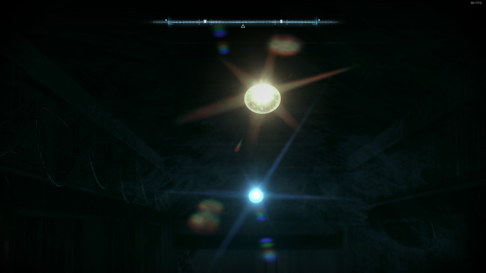
As you may have noticed, there is another effect on lights: a glare is visible on bright light sources. Let's take a look at an example to understand it better.
Below are two lights having their own glare effect (the game final resolution is 1920x1080 here).
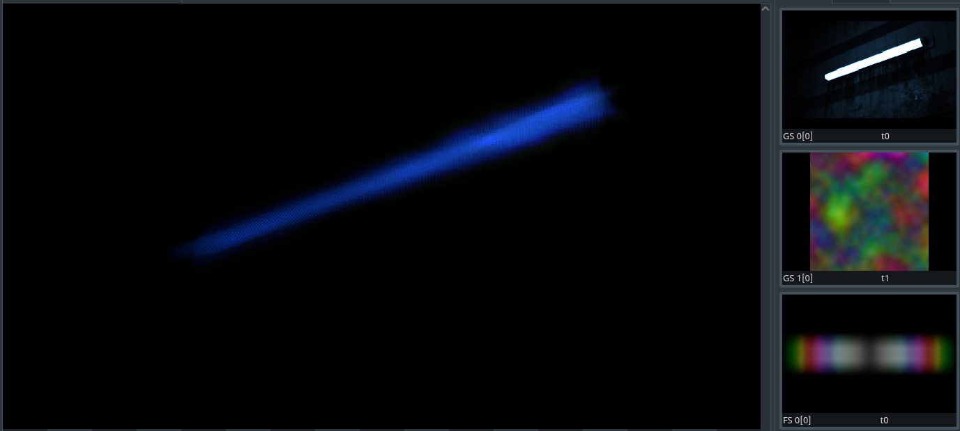
If we take a look in RenderDoc at the final buffer (bloom + lens-flare) before it is composited with the rest we can see this that the glare effect is actually part of it too. This means it is a post-process as well and not based on a sprite/particle system !
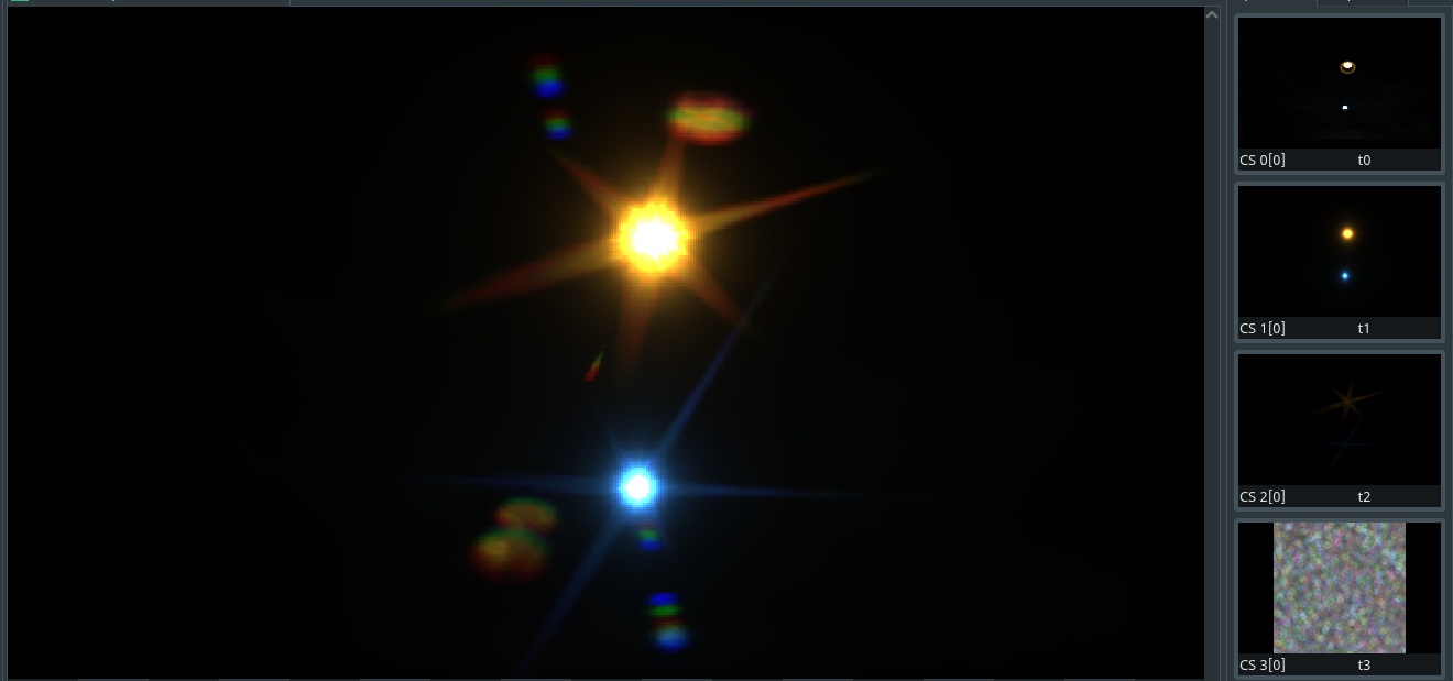
In the image above, the left side shows the final buffer result (slightly scaled to compensate HDR values) where the ghosts have been generated. On the right side we can see the several texture as inputs:
So the glare effect is built before the ghosts. It is made just in the middle of the down then upscale process that generates the bloom result. That glare buffer is 1/4 of the game resolution and looks like this:
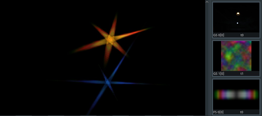
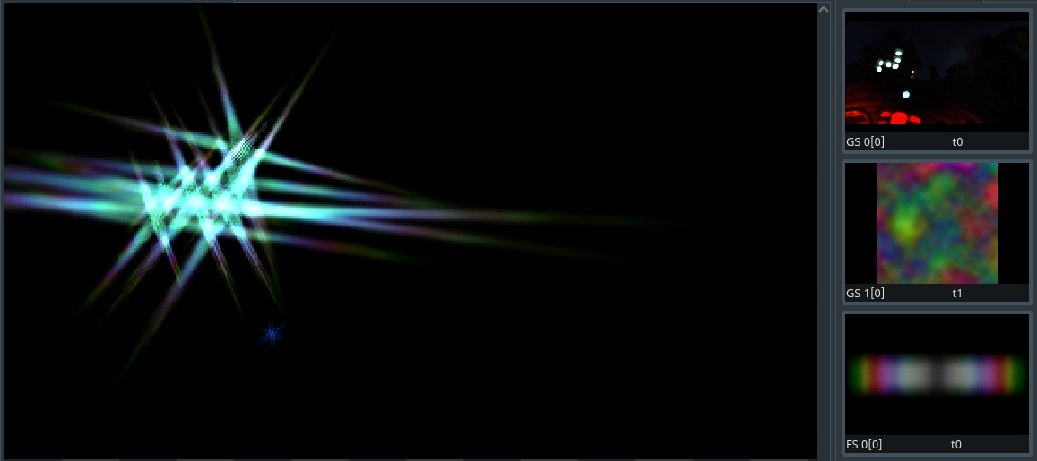
Once again you can see the buffer result on the left and its inputs on the right:
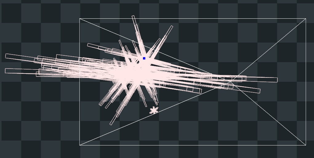
Looking at the buffer result isn't enough to understand how it has been generated. Switching views in RenderDoc allows to see this:
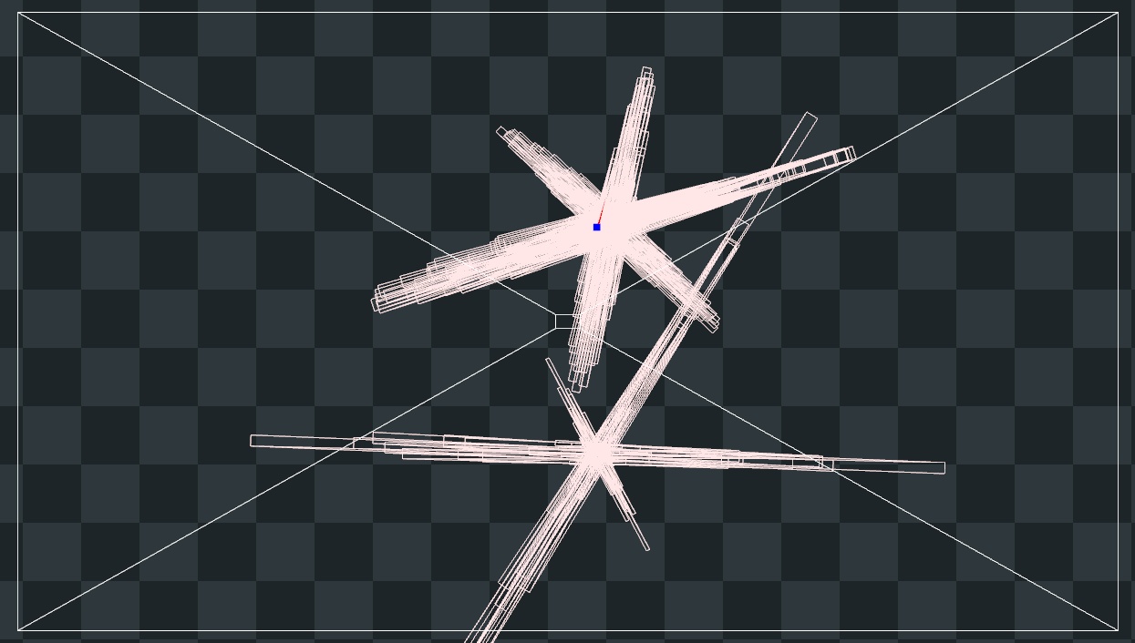
(This specific pass was rendered in 0.04388ms on my GPU)
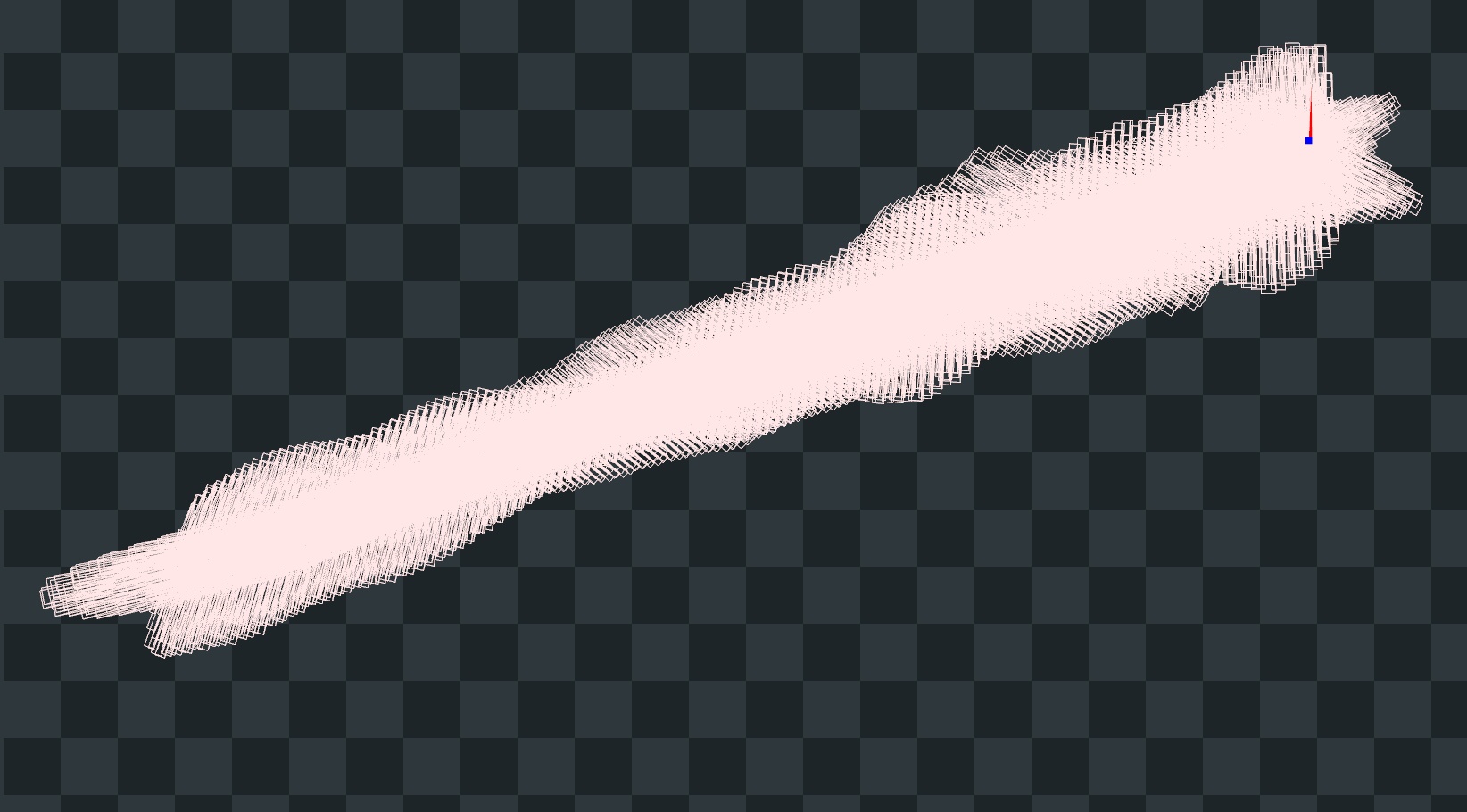
So glares are actually made from geometry, via a lot of quads with different orientations and sizes to draw the star shape. Like I mentioned previously, this buffer is 1/4 of the game resolution, which translates to a size of 480x270 pixels. This means 129600 pixels in total. This number matters because if we divide it by 4 we get 32400 which is the exact number of vertices drawn in the vertex shader of this pass:
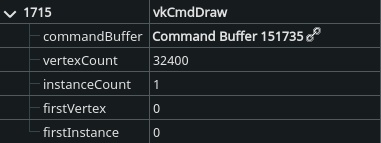
(Batman doesn't run via Vulkan of course, but the Linux translation layer does.)
The primitive type used here is points and not triangles, which means each vertex is independent and likely read a block of 2x2 pixels to average the luminosity. If this luminosity goes above a certain threshold, then the next phase which is the geometry shader will generates one or several quads to draw the shape of the glare. Then each quad during the pixel shader phase samples the gradient texture seen above multiplied by the color of input buffer to adapt to the source light color.
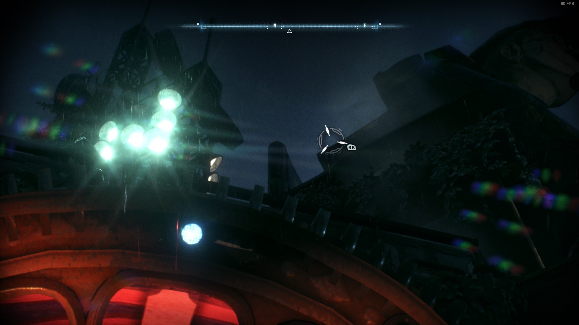
The size of the quads depends on the luminosity, for example with this neon light below the quads are very small (but dense given how large the light fills the screen and gets captured by the points).
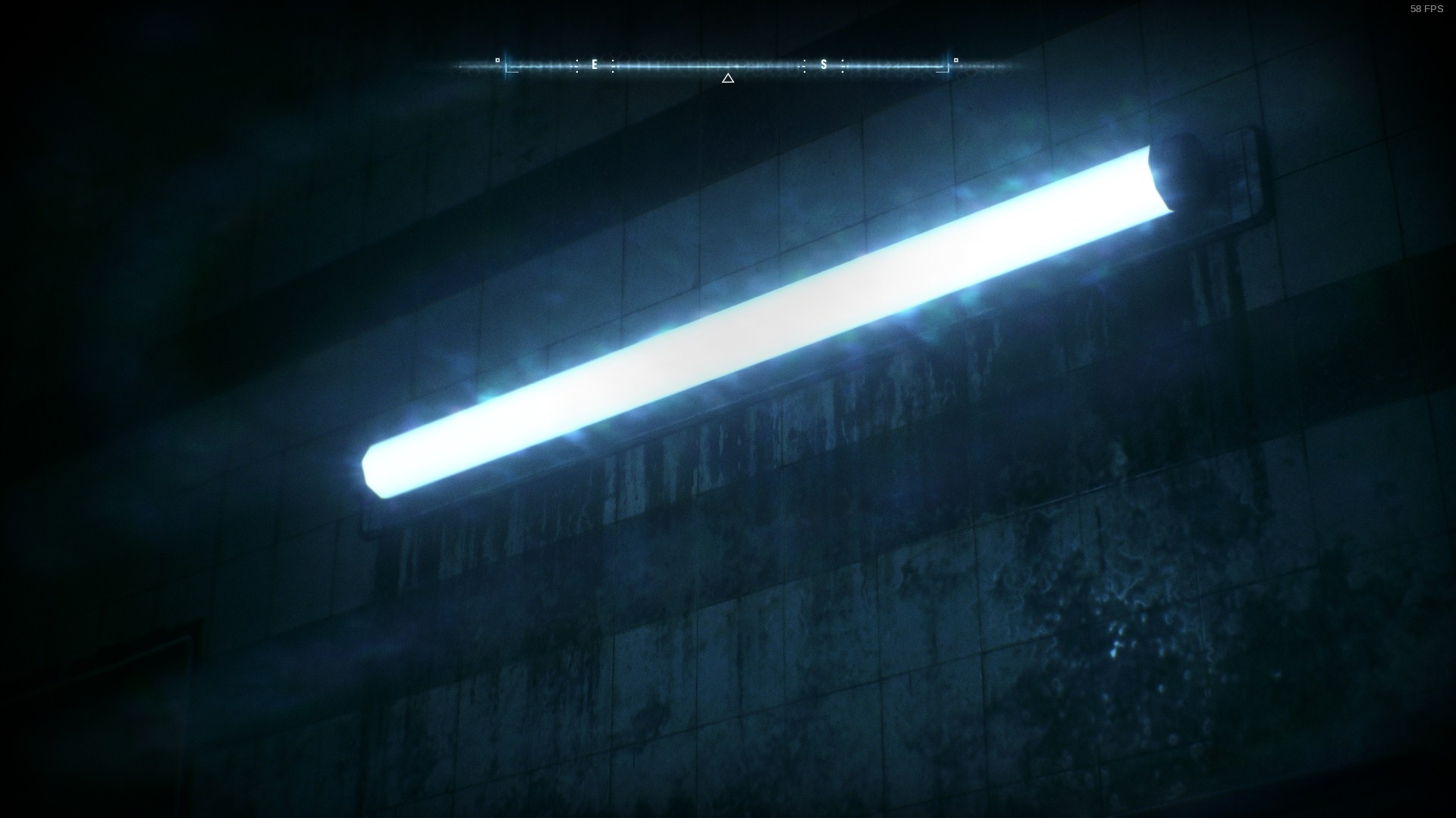
(Render time: 0.06864ms)
Another example:
(Render time: 0.0698ms)
Here is what it looks like in movement:
While this effect looks good and cheap, there is a caveat to be aware of. Because of the way the glare is built, when moving the camera the bright pixels will move and at low resolution this can introduce some kind of flicker. Therefor the size of the quad will pulse. This is visible in Batman when moving slowing:
(See how the left branch here rotate in a blocky way)
From my observations, it seems bright lights lose in intensity when they are far away which leads to smaller quads and therefore hide the glare and its issue. This could be simply because how the way the buffer is downsampled before hand, or because light actually change in intensity in-game.
I also think the buffer is oversampled when mixed with the ghosts to blur it slightly and reduce the stepping.
And finally, the fact the glare shape change size and orientation based on the screen position is another good way to hide the artifact via the motion. I had to find very specific angles and camera movements to make the issue noticeable enough.
Let's take the time to review how UE4 default lens-flare effect works because it does several interesting things (but some bad stuff too). It can be summarized with this little scheme:
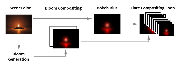
And here are the steps in details:
1 - Bloom Generation
Bloom is generated just before lens-flares. If the bloom intensity is 0, then neither bloom nor lens-flares will be rendered. If the threshold for the bloom is -1, then no processing is done and one the Scene Color downsamples is used as-is. If there is a threshold specified a different process generates the bloom effect. The result is then fed to the lens-flare rendering code.
2 - Bloom Compositing
An empty render target is created and the bloom is copied into it. The render target has the same size as the bloom, which is half of the viewport resolution (1/2). This size can change depending on the engine scalability settings (aka performance tweaks).
3 - Bokeh Blur
This pass uses the downsampled buffer as input and render a blurry version with the help an shape (the bokeh texture).
The blur itself is generated by drawing an instanced quad for (almost) each pixel. It is basically a sprite with the bokeh texture and the color sampled from the input texture. The drawing is discarded by setting the quad size to 0 if the pixel luminosity is below the threshold value. The comparison with the threshold value is binary, which can introduce flickering if the luminosity is unstable (like when the camera moves slightly):
(Here is the raw output of a small bokeh blur in a corner of the screen)
Adjusting the blur size simply means changing the size of the quad drawn. This is why a large blur radius cost more because of how many quads will overlap (overdraw). This is also why a very small blur size leads to... nothing ! Simply because the quad becomes too small and isn't rasterized anymore (smaller than a pixel).
To keep performance reasonable this pass is done in a render target that is a quarter of the viewport (1/4, but again dependent on scalability settings) and only 1 over 2 pixels is actually drawn. This is why when using a very small blur size a checker pattern can appear:
Another important point to note is that inside this render target the actual drawing area is half of the buffer. This is to ensure that any quad drawn will not end-up cut at the buffer edges. This means the actual drawing is therefore done at 1/8 of the viewport size.
4 - Flare Accumulation
A loop draws several time additively into the render target with the copy of the bloom a scaled quad with the bokeh blur pass result. The loop is on the code side (CPU) and not in a shader (GPU).
Each iteration of the loop use a color and size inherited from the post-process volume settings. The size is base don the alpha value of the color. With some math magic, the quad is drawn normally the value is greater than 0.5, otherwise it will be drawn upside down (scaled negatively to give the mirrored light effect of the ghost).
Since the size of the flare can be smaller than the viewport, this is why it matters that the borders of the blur pass remain clean and not clipped, or they would be easily visible.
(In this example I'm using a radial gradient as the bokeh texture)
I'm still wondering why the drawing is done in several passes rather than a single one. I thought it could be a way to save some bandwidth to avoid redrawing too much the buffer, but since the actual content is scaled down you have to oversize it to compensate. This lead to updating some pixels for nothing. Maybe it is intentional, or maybe it is just legacy code that hasn't been cleaned up.
5 - Output
Finally, the engine retrieve the render target and composite it into the final frame, before the tone-mapping step. All the passes are done in render targets with floating point precision to work with -and preserve- HDR values.
Wait, there is more...
On top of all of that there is an additional behavior to take into account: sub-region rendering.
When running the editor, the engine allocates a render target which match the viewport size. However when switching to fullscreen or opening a secondary window with a different viewport (like the static mesh viewer) the render target will be resized to accommodate the new resolution. When closing the window or exiting the full screen mode, the engine won't resize (down) the render target.
Instead it will only render a smaller part of it (a region). This avoid the need to reallocate/rebuild a render target all the time while being able to render at the right resolution. Unfortunately this complicate a bit the shaders later...
Now here is a little overview of how my own lens-flares work. Each image represents a different rendering pass:
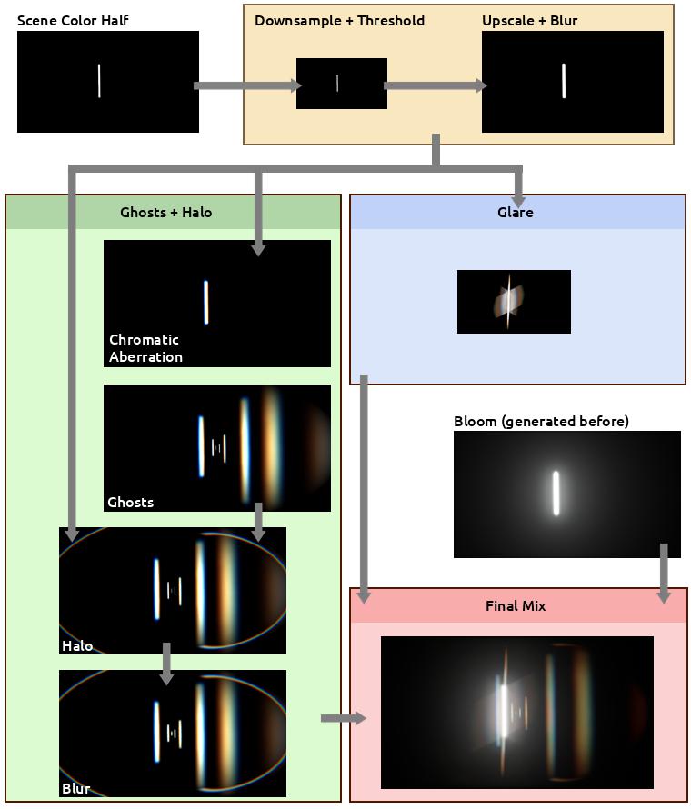
The process is divided in a few big steps:
Something to be aware: this article is divided in steps to make reading and comprehension easier. Those are not steps that can followed to compile code on the way as many parts will be missing until reaching the end.
I also strongly advise to read all the steps first before trying to copy/paste anything.
Because of the way the Unreal Engine manages external shaders, we are gonna need to setup a custom plugin.
Shader files (not Materials) are usually stored in the engine folder, but it is possible to reference them externally via a module or plugin. It is not possible to reference them directly in your project code because they need to be loaded earlier by the engine.
While a module inside the project folder can work, I found a plugin easier to setup and produce less conflicts/overlaps with a project in general.
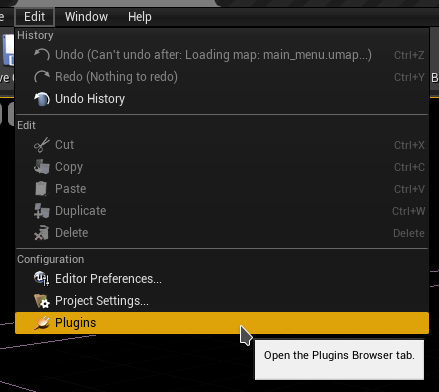
Hop in the editor and open the plugin manager:
Then click on the New Plugin button at the bottom of the window:

Make sure to choose a blank plugin, then name it (in my case I used CustomPostProcess):
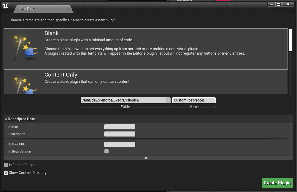
You can fill in the other information, just make sure that "Is Engine Plugin" is disabled. Then use Create Plugin to build the plugin.
Open the folder where the plugin has been created (it should be in your project Plugins folder). Then locate and open the Build.cs file in the Source folder (mine is CustomPostProcess.Build.cs) and add the following includes:
    PrivateIncludePaths.AddRange(
        new string[]
        {
            // Needed to include the engine Lens Flare post-process header
            EngineDirectory + "/Source/Runtime/Renderer/Private"
        }
        );

    PublicDependencyModuleNames.AddRange(
        new string[]
        {
            // Needed for RenderGraph, PostProcess, Shaders
            "Core",
            "RHI",
            "Renderer",
            "RenderCore",
            "Projects"
        }
        );
By default there should be a class named like the plugin. Open the class files and edit them with the following:
CustomPostProcess.h
#pragma once

#include "CoreMinimal.h"
#include "Modules/ModuleManager.h"

class FCustomPostProcessModule : public IModuleInterface
{
    public:
        virtual void StartupModule() override;
        virtual void ShutdownModule() override;
};
CustomPostProcess.cpp
#include "CustomPostProcess.h"
#include "Interfaces/IPluginManager.h"

#define LOCTEXT_NAMESPACE "FCustomPostProcessModule"

void FCustomPostProcessModule::StartupModule()
{
    FString BaseDir = IPluginManager::Get().FindPlugin(TEXT("CustomPostProcess"))->GetBaseDir();
    FString PluginShaderDir = FPaths::Combine( BaseDir, TEXT("Shaders") );
    AddShaderSourceDirectoryMapping(TEXT("/CustomShaders"), PluginShaderDir);
}

void FCustomPostProcessModule::ShutdownModule()
{
}

#undef LOCTEXT_NAMESPACE

IMPLEMENT_MODULE(FCustomPostProcessModule, CustomPostProcess)
In StartupModule() we retrieve the Plugin location to which we append the Shaders folder we just created. Then by calling AddShaderSourceDirectoryMapping() we create a symbolic path for the engine to know where to look for to load our custom shader files.
Last part of the setup is to make sure the .uplugin file is correctly configured, so open it and make sure the Modules property is set as follow:
    "Modules": [
        {
            "Name": "CustomPostProcess",
            "Type": "Runtime",
            "LoadingPhase": "PostConfigInit"
        }
    ]
Make sure to adjust all the mentions of CustomPostProcess with your own plugin name in the snippets shown above.
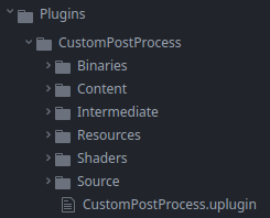
In the plugin root folder add a new folder named Shaders, sitting next to the Content and Source ones:
This is where we are going to store the shader files needed by the rendering passes. Create the following text files (take note of the file extension):
.USF
- Chroma.usf
- DownsampleThreshold.usf
- DualKawaseBlur.usf
- Ghosts.usf
- Glare.usf
- Mix.usf
- Halo.usf
- Rescale.usf
- ScreenPass.usf
.USH
- Shared.ush
Open Shared.ush and paste this into it:
// Not sure if this one is needed, but the engine
// lens-flare shaders have it too.
#define SCENE_TEXTURES_DISABLED 1

#include "/Engine/Public/Platform.ush"
#include "/Engine/Private/Common.ush"
#include "/Engine/Private/ScreenPass.ush"
#include "/Engine/Private/PostProcessCommon.ush"

Texture2D InputTexture;
SamplerState InputSampler;
float2 InputViewportSize;
These are common variables and defines that are gonna be used across all the passes. The other files will be covered in the next parts.
Usually to control post-process settings you need to pass by a post-process settings struct which can be seen in post-process volumes or cameras. I edited this struct in the past to add custom settings, like for my anamorphic bloom, but it presented several issues:
These few points make editing this struct very annoying, time consuming and easy to broke. Hence why I didn't want to go this way this time.
Instead I preferred to focus on another method which would be much more future proof while still being user friendly for artists to edit settings in-engine (and in-editor as well). I went with a combined solution of:
This doesn't offer the flexibility of post-process volumes which could adapt to specific area of a level, but I figured that Bloom and lens-flare wouldn't change much (except maybe for the threshold value in specific context). Therefore updating a few settings can be done manually via code or Blueprint scripting in a level. To my eyes, this is a good trade-of between artist control and code maintenance.
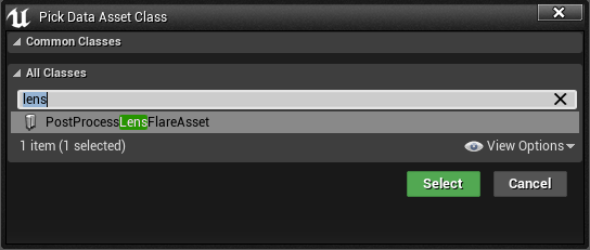
I will cover the console variable later, so for now let's prepare the data asset. To do so, create a new class inheriting DataAsset. I named my own PostProcessLensFlareAsset:
PostProcessLensFlareAsset.h
#pragma once

#include "CoreMinimal.h"
#include "Engine/DataAsset.h"
#include "PostProcessLensFlareAsset.generated.h"

// This custom struct is used to more easily
// setup and organize the settings for the Ghosts
USTRUCT(BlueprintType)
struct FLensFlareGhostSettings
{
    GENERATED_BODY()

    UPROPERTY(EditAnywhere, BlueprintReadWrite, Category="Exedre")
    FLinearColor Color = FLinearColor::White;

    UPROPERTY(EditAnywhere, BlueprintReadWrite, Category="Exedre")
    float Scale = 1.0f;
};


UCLASS()
class CUSTOMPOSTPROCESS_API UPostProcessLensFlareAsset : public UDataAsset
{
    GENERATED_BODY()

    public:
        UPROPERTY(EditAnywhere, Category="General", meta=(UIMin = "0.0", UIMax = "10.0"))
        float Intensity = 1.0f;

        UPROPERTY(EditAnywhere, Category="General")
        FLinearColor Tint = FLinearColor(1.0f, 0.85f, 0.7f, 1.0f);

        UPROPERTY(EditAnywhere, Category="General")
        UTexture2D* Gradient = nullptr;


        UPROPERTY(EditAnywhere, Category="Threshold", meta=(UIMin = "0.0", UIMax = "10.0"))
        float ThresholdLevel = 1.0f;

        UPROPERTY(EditAnywhere, Category="Threshold", meta=(UIMin = "0.01", UIMax = "10.0"))
        float ThresholdRange = 1.0f;


        UPROPERTY(EditAnywhere, Category="Ghosts", meta=(UIMin = "0.0", UIMax = "1.0"))
        float GhostIntensity = 1.0f;

        UPROPERTY(EditAnywhere, Category="Ghosts", meta=(UIMin = "0.0", UIMax = "1.0"))
        float GhostChromaShift = 0.015f;

        UPROPERTY(EditAnywhere, Category="Ghosts")
        FLensFlareGhostSettings Ghost1 = { FLinearColor(1.0f, 0.8f, 0.4f, 1.0f), -1.5 };

        UPROPERTY(EditAnywhere, Category="Ghosts")
        FLensFlareGhostSettings Ghost2 = { FLinearColor(1.0f, 1.0f, 0.6f, 1.0f),  2.5 };

        UPROPERTY(EditAnywhere, Category="Ghosts")
        FLensFlareGhostSettings Ghost3 = { FLinearColor(0.8f, 0.8f, 1.0f, 1.0f), -5.0 };

        UPROPERTY(EditAnywhere, Category="Ghosts")
        FLensFlareGhostSettings Ghost4 = { FLinearColor(0.5f, 1.0f, 0.4f, 1.0f), 10.0 };

        UPROPERTY(EditAnywhere, Category="Ghosts")
        FLensFlareGhostSettings Ghost5 = { FLinearColor(0.5f, 0.8f, 1.0f, 1.0f),  0.7 };

        UPROPERTY(EditAnywhere, Category="Ghosts")
        FLensFlareGhostSettings Ghost6 = { FLinearColor(0.9f, 1.0f, 0.8f, 1.0f), -0.4 };

        UPROPERTY(EditAnywhere, Category="Ghosts")
        FLensFlareGhostSettings Ghost7 = { FLinearColor(1.0f, 0.8f, 0.4f, 1.0f), -0.2 };

        UPROPERTY(EditAnywhere, Category="Ghosts")
        FLensFlareGhostSettings Ghost8 = { FLinearColor(0.9f, 0.7f, 0.7f, 1.0f), -0.1 };


        UPROPERTY(EditAnywhere, Category="Halo", meta=(UIMin = "0.0", UIMax = "1.0"))
        float HaloIntensity = 1.0f;

        UPROPERTY(EditAnywhere, Category="Halo", meta=(UIMin = "0.0", UIMax = "1.0"))
        float HaloWidth = 0.6f;

        UPROPERTY(EditAnywhere, Category="Halo", meta=(UIMin = "0.0", UIMax = "1.0"))
        float HaloMask = 0.5f;

        UPROPERTY(EditAnywhere, Category="Halo", meta=(UIMin = "0.0", UIMax = "1.0"))
        float HaloCompression = 0.65f;

        UPROPERTY(EditAnywhere, Category="Halo", meta=(UIMin = "0.0", UIMax = "1.0"))
        float HaloChromaShift = 0.015f;


        UPROPERTY(EditAnywhere, Category="Glare", meta=(UIMin = "0", UIMax = "10"))
        float GlareIntensity = 0.02f;

        UPROPERTY(EditAnywhere, Category="Glare", meta=(UIMin = "0.01", UIMax = "200"))
        float GlareDivider = 60.0f;

        UPROPERTY(EditAnywhere, Category="Glare", meta=(UIMin = "0.0", UIMax = "10.0"))
        FVector GlareScale = FVector( 1.0f, 1.0f, 1.0f );

        UPROPERTY(EditAnywhere, Category="Glare")
        FLinearColor GlareTint = FLinearColor(1.0f, 1.0f, 1.0f, 1.0f);

        UPROPERTY(EditAnywhere, Category="Glare")
        UTexture2D* GlareLineMask = nullptr;
};
Not much to say on the Data Asset itself in term of code, it's mostly variables with their default values. Compile the code and launch the editor.
In the editor, right-click in the content browser and look for the Data Asset type:
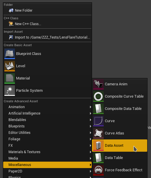
Then choose the new class that was just created:
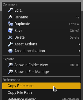
Save it, then righ-click and choose Copy Reference to get the asset path into your clipboard. Store it somewhere as we will need this asset path reference later in the code.
I suggest creating the asset in the content folder of the plugin and not the project. That makes it easier to reference the asset and move the plugin in other projects.
The data asset not only defines values, it also references two textures:

As with the data asset, I recommend saving these resources inside the plugin's content folder.
A point I didn't really focus on yet is how the post-process pipeline wasn't meant to be heavily customized. That's why it requires to edit the engine code a bit unfortunately.
In terms of implementation, since a few engine versions (4.24 I believe), the post-process system of UE4 migrated to the Render Dependency Graph (RDG). RDG is basically a tool that compile each frame the tasks that will be sent to the GPU. This simplify greatly the writing of custom render passes as RDG manages a lot of things for us.
I started by modifying the existing code of the lens-flare post-process, overwriting the engine render pass to build my own. That works, and I learned tons of stuff with it, but like other things it could become complicated to maintain.
Instead we can build a delegate function. Its goal is to offer a hook into the engine rendering process to insert our own code from an external code pass. This makes possible to have our own lens-flare rendering in our project directly and have it called by the engine when it's time to render it. This means changes are minimal and simple on the engine side.
To start, open the engine file Engine/Source/Runtime/Renderer/Private/PostProcess/PostProcessLensFlares.h.
In this header there is a struct named FLensFlareInputs to which we need to add a parameter. This struct is used to send a few settings from the general post-process rendering phase into the rendering pass itself. So we need to add the SceneColor input since we want to make our own threshold pass. I inserted it between the Bloom and Flare inputs:
struct FLensFlareInputs
{
    static const uint32 LensFlareCountMax = 8;

    // [Required] The bloom convolution texture. If enabled, this will be composited with lens flares. Otherwise,
    // a transparent black texture is used instead. Either way, the final output texture will use the this texture
    // descriptor and viewport.
    FScreenPassTexture Bloom;

    // Froyok
    // Scene color at half resolution
    FScreenPassTexture HalfSceneColor;

    // [Required] The scene color input, before bloom, which is used as the source of lens flares.
    // This can be a downsampled input based on the desired quality level.
    FScreenPassTexture Flare;
[...]
Next, just below the struct we modified, add a new struct as follow:
// Froyok
struct FLensFlareOutputsData
{
    FRDGTextureRef Texture;
    FIntRect Rect;
};
This struct will be used to send back data to the post-process rendering pass from our custom code sitting outside of the engine.
Finally at the bottom of the file there should be a second AddLensFlaresPass() definition to which we add the Scene Color input as well:
// Helper function which pulls inputs from the post process settings of the view.
FScreenPassTexture AddLensFlaresPass(
    FRDGBuilder& GraphBuilder,
    const FViewInfo& View,
    FScreenPassTexture Bloom,
    FScreenPassTexture HalfSceneColor, // Froyok
    const FSceneDownsampleChain& SceneDownsampleChain);
This function is called by the general Post Process pipeline and used to build the struct we modified above.
Before diving into the callback details, let's finish the setup of the Scene Color setting. So let's jump into Engine/Source/Runtime/Renderer/Private/PostProcess/PostProcessing.cpp. Look for the AddLensFlaresPass() call and add the Scene Color variable:
FScreenPassTexture LensFlares = AddLensFlaresPass(
    GraphBuilder,
    View,
    Bloom,
    HalfResolutionSceneColor, // Froyok
    *PassInputs.SceneDownsampleChain
);
If you are curious, you can take the time to look around in the code to see how things work.
Note: in UE5 the variable name for the scene color is now DownsampledSceneColor instead of HalfResolutionSceneColor. Make sure to adjust your code accordingly.
Also if Temporal Anti-Aliasing is disabled in your project, the half resolution SceneColor will be invalid. So fall back to SceneColor.Texture instead.
We can now go over /Engine/Source/Runtime/Renderer/Private/PostProcess/PostProcessLensFlares.cpp. Right at the beginning of the file, just after the includes, we can insert the delegate declaration:
#include "PostProcessLensFlares.h"
#include "PostProcessDownsample.h"

// Froyok
DECLARE_MULTICAST_DELEGATE_FourParams( FPP_LensFlares, FRDGBuilder&, const FViewInfo&, const FLensFlareInputs&, FLensFlareOutputsData& );
RENDERER_API FPP_LensFlares PP_LensFlares;
Delegates are basically a way to reference a function from another point of code, it even can be done dynamically at runtime. For more information check out the documentation.
The DECLARE_MULTICAST_DELEGATE_FourParams is a macro which specifies we want to define a function call with 4 parameters. I'm not going over the parameters themselves here as we will see them in a next step.
To make comparison easier and help debugging things I added a console variable that allows to switch between the old lens-flare and the new ones. So just below the existing cvar (console variable) at the top of the file add another one like this:
[...]
const int32 GLensFlareQuadsPerInstance = 4;

TAutoConsoleVariable<int32> CVarLensFlareQuality(
    TEXT("r.LensFlareQuality"),
    2,
    TEXT(" 0: off but best for performance\n")
    TEXT(" 1: low quality with good performance\n")
    TEXT(" 2: good quality (default)\n")
    TEXT(" 3: very good quality but bad performance"),
    ECVF_Scalability | ECVF_RenderThreadSafe);

// Froyok
// Console var to switch between the lens-flare methods
TAutoConsoleVariable<int32> CVarLensFlareMethod(
    TEXT("r.LensFlareMethod"),
    1,
    TEXT(" 0: Original lens-flare method\n")
    TEXT(" 1: Custom lens-flare method"),
    ECVF_RenderThreadSafe);
[...]
Scroll down in the file near the bottom and look for the AddLensFlaresPass() function but that one with the SceneDownsampleChain input, because we need to add the Scene Color input too:
FScreenPassTexture AddLensFlaresPass(
    FRDGBuilder& GraphBuilder,
    const FViewInfo& View,
    FScreenPassTexture Bloom,
    FScreenPassTexture HalfSceneColor, // Froyok
    const FSceneDownsampleChain& SceneDownsampleChain)
{
    const ELensFlareQuality LensFlareQuality = GetLensFlareQuality();

    const FPostProcessSettings& Settings = View.FinalPostProcessSettings;
[...]
Next scroll down to where the LensFlareInputs is declared and feed it the Scene Color:
[...]
FLensFlareInputs LensFlareInputs;
LensFlareInputs.Bloom = Bloom;
LensFlareInputs.HalfSceneColor = HalfSceneColor; // Froyok
LensFlareInputs.Flare = SceneDownsampleChain.GetTexture(LensFlareDownsampleStageIndex);
[...]
Finally we change the original code from this:
[...]
    // If a bloom output texture isn't available, substitute the half resolution scene color instead, but disable bloom
    // composition. The pass needs a primary input in order to access the image descriptor and viewport for output.
    if (!Bloom.IsValid())
    {
        LensFlareInputs.Bloom = SceneDownsampleChain.GetFirstTexture();
        LensFlareInputs.bCompositeWithBloom = false;
    }

    return AddLensFlaresPass(GraphBuilder, View, LensFlareInputs);
}
Into this:
    // If a bloom output texture isn't available, substitute the half resolution scene color instead, but disable bloom
    // composition. The pass needs a primary input in order to access the image descriptor and viewport for output.
    if (!Bloom.IsValid())
    {
        LensFlareInputs.Bloom = SceneDownsampleChain.GetFirstTexture();
        LensFlareInputs.bCompositeWithBloom = false;
    }

    // Froyok
    int32 UseCustomFlare = CVarLensFlareMethod.GetValueOnRenderThread();

    FLensFlareOutputsData Outputs;
    Outputs.Texture = nullptr;
    Outputs.Rect    = FIntRect(0,0,0,0);

    if( UseCustomFlare != 0 )
    {
        PP_LensFlares.Broadcast( GraphBuilder, View, LensFlareInputs, Outputs );
    }

    if( UseCustomFlare == 0 || Outputs.Texture == nullptr )
    {
        return AddLensFlaresPass(GraphBuilder, View, LensFlareInputs);
    }
    else
    {
        return FScreenPassTexture( Outputs.Texture, Outputs.Rect );
    }
}
Here is what happens here:
You can even compile and run the engine/editor. Nothing will have changed visually but we now have a way to hook into the fens-flare pass.
Like I mentioned I kept the original lens-flare code pass for debug purpose, but on a more mature project I would suggest removing this pass altogether. Especially since it requires compiling shaders that may never be used, etc.
Now that the hook is in place, we need a place to manage our own rendering code. I initially went with the Game Instance class of my project but going this route meant that the lens-flare code wouldn't run until the game itself is running (or it may not be properly updated). I wanted something that would work in any context in-editor. Plus it would create difficulties with the Global Shader references.
The solution I went for instead was to create an Engine Subsystem. Subsystems are singleton managed by the engine itself which can be easily retrieved from anywhere in the game code. There are different type depending on the context they live in. The particularity of the engine subsystem is that is starts and stops with the engine, making it compatible with the editor context.
So create a new class inherited from EngineSubsystem in the plugin. Mine is simply called PostProcessSubsystem.
PostProcessSubsystem.h
#pragma once

#include "CoreMinimal.h"
#include "PostProcess/PostProcessLensFlares.h" // For PostProcess delegate
#include "PostProcessSubsystem.generated.h"

DECLARE_MULTICAST_DELEGATE_FourParams( FPP_LensFlares, FRDGBuilder&, const FViewInfo&, const FLensFlareInputs&, FLensFlareOutputsData& );
extern RENDERER_API FPP_LensFlares PP_LensFlares;

class UPostProcessLensFlareAsset;

UCLASS()
class MYPROJECT_API UPostProcessSubsystem : public UEngineSubsystem
{
    GENERATED_BODY()

    public:
        // Init function to setup the delegate and load the data asset
        virtual void Initialize(FSubsystemCollectionBase& Collection) override;

        // Used for cleanup
        virtual void Deinitialize() override;

    private:
        // The reference to the data asset storing the settings
        UPROPERTY(Transient)
        UPostProcessLensFlareAsset* PostProcessAsset;

        // Called by engine delegate Render Thread
        void RenderLensFlare(
            FRDGBuilder& GraphBuilder,
            const FViewInfo& View,
            const FLensFlareInputs& Inputs,
            FLensFlareOutputsData& Outputs
        );

        // Threshold prender pass
        FRDGTextureRef RenderThreshold(
            FRDGBuilder& GraphBuilder,
            FRDGTextureRef InputTexture,
            FIntRect& InputRect,
            const FViewInfo& View
        );

        // Ghosts + Halo render pass
        FRDGTextureRef RenderFlare(
            FRDGBuilder& GraphBuilder,
            FRDGTextureRef InputTexture,
            FIntRect& InputRect,
            const FViewInfo& View
        );

        // Glare render pass
        FRDGTextureRef RenderGlare(
            FRDGBuilder& GraphBuilder,
            FRDGTextureRef InputTexture,
            FIntRect& InputRect,
            const FViewInfo& View
        );

        // Sub-pass for blurring
        FRDGTextureRef RenderBlur(
            FRDGBuilder& GraphBuilder,
            FRDGTextureRef InputTexture,
            const FViewInfo& View,
            const FIntRect& Viewport,
            int BlurSteps
        );

        // Cached blending and sampling states
        // which are re-used across render passes
        FRHIBlendState* ClearBlendState = nullptr;
        FRHIBlendState* AdditiveBlendState = nullptr;

        FRHISamplerState* BilinearClampSampler = nullptr;
        FRHISamplerState* BilinearBorderSampler = nullptr;
        FRHISamplerState* BilinearRepeatSampler = nullptr;
        FRHISamplerState* NearestRepeatSampler = nullptr;
};
Let's review a few things here:
PostProcessSubsystem.cpp
#include "PostProcessSubsystem.h"
#include "PostProcessLensFlareAsset.h"

#include "RenderGraph.h"
#include "ScreenPass.h"
#include "PostProcess/PostProcessLensFlares.h"

namespace
{
    // TODO_SHADER_SCREENPASS

    // TODO_SHADER_RESCALE

    // TODO_SHADER_DOWNSAMPLE

    // TODO_SHADER_KAWASE

    // TODO_SHADER_CHROMA

    // TODO_SHADER_GHOSTS

    // TODO_SHADER_HALO

    // TODO_SHADER_GLARE

    // TODO_SHADER_MIX
}

void UPostProcessSubsystem::Initialize( FSubsystemCollectionBase& Collection )
{
    Super::Initialize( Collection );

    //--------------------------------
    // Delegate setup
    //--------------------------------
    FPP_LensFlares::FDelegate Delegate = FPP_LensFlares::FDelegate::CreateLambda(
        [=]( FRDGBuilder& GraphBuilder, const FViewInfo& View, const FLensFlareInputs& Inputs, FLensFlareOutputsData& Outputs )
    {
        RenderLensFlare(GraphBuilder, View, Inputs, Outputs);
    });

    ENQUEUE_RENDER_COMMAND(BindRenderThreadDelegates)([Delegate](FRHICommandListImmediate& RHICmdList)
    {
        PP_LensFlares.Add(Delegate);
    });


    //--------------------------------
    // Data asset loading
    //--------------------------------
    FString Path = "PostProcessLensFlareAsset'/CustomPostProcess/DefaultLensFlare.DefaultLensFlare'";

    PostProcessAsset = LoadObject<UPostProcessLensFlareAsset>( nullptr, *Path );
    check(PostProcessAsset);
}


void UPostProcessSubsystem::Deinitialize()
{
    ClearBlendState = nullptr;
    AdditiveBlendState = nullptr;
    BilinearClampSampler = nullptr;
    BilinearBorderSampler = nullptr;
    BilinearRepeatSampler = nullptr;
    NearestRepeatSampler = nullptr;
}
The namespace is used to declare our global shaders without producing any conflicts with any existing ones on the engine side. The TODOs here will be replaced by actual code in the next steps.
Bellow that, the Initialize() function does two big things:
I have been told that the way I setup and connect the delegate here may not be thread safe. I didn't encounter any crashes related to that issue myself, but be aware that this code may not be suited for production as-is.
A suggestion I received to fix this problem (which I may do in the future and update the article) is to move the rendering code into a sub-class and store it in a thread safe pointer (TSharedPtr) made with CreateShared().
Each render pass use the same basics and the original engine code has a tendency of copy/pasting the same code. So to cleanup and make things easier for iteration I factored some code into more convenient to use functions that are then used by each pass. The following functions are added as-is in the PostProcessSubsystem.cpp (without the need to declare them in the header).
The goal of this function is to compute the sub-region size and output a scale to rescale the buffer. This will be useful in-editor during the Threshold pass. Most of the code is copy pasted from the engine itself (see the comment).
FVector2D GetInputViewportSize( const FIntRect& Input, const FIntPoint& Extent )
{
    // Based on
    // GetScreenPassTextureViewportParameters()
    // Engine/Source/Runtime/Renderer/Private/ScreenPass.cpp

    FVector2D ExtentInverse = FVector2D(1.0f / Extent.X, 1.0f / Extent.Y);

    FVector2D RectMin = FVector2D(Input.Min);
    FVector2D RectMax = FVector2D(Input.Max);

    FVector2D Min = RectMin * ExtentInverse;
    FVector2D Max = RectMax * ExtentInverse;

    return (Max - Min);
}
Next is the most important function: it's the actual draw that will be registered to the Render Graph:
// The function that draw a shader into a given RenderGraph texture
template<typename TShaderParameters, typename TShaderClassVertex, typename TShaderClassPixel>
inline void DrawShaderPass(
        FRDGBuilder& GraphBuilder,
        const FString& PassName,
        TShaderParameters* PassParameters,
        TShaderMapRef<TShaderClassVertex> VertexShader,
        TShaderMapRef<TShaderClassPixel> PixelShader,
        FRHIBlendState* BlendState,
        const FIntRect& Viewport
    )
{
    const FScreenPassPipelineState PipelineState(VertexShader, PixelShader, BlendState);

    GraphBuilder.AddPass(
        FRDGEventName( TEXT("%s"), *PassName ),
        PassParameters,
        ERDGPassFlags::Raster,
        [PixelShader, PassParameters, Viewport, PipelineState] (FRHICommandListImmediate& RHICmdList)
    {
        RHICmdList.SetViewport(
            Viewport.Min.X, Viewport.Min.Y, 0.0f,
            Viewport.Max.X, Viewport.Max.Y, 1.0f
        );

        SetScreenPassPipelineState(RHICmdList, PipelineState);

        SetShaderParameters(
            RHICmdList,
            PixelShader,
            PixelShader.GetPixelShader(),
            *PassParameters
        );

        DrawRectangle(
            RHICmdList,                             // FRHICommandList
            0.0f, 0.0f,                             // float X, float Y
            Viewport.Width(),   Viewport.Height(),  // float SizeX, float SizeY
            Viewport.Min.X,     Viewport.Min.Y,     // float U, float V
            Viewport.Width(),                       // float SizeU
            Viewport.Height(),                      // float SizeV
            Viewport.Size(),                        // FIntPoint TargetSize
            Viewport.Size(),                        // FIntPoint TextureSize
            PipelineState.VertexShader,             // const TShaderRefBase VertexShader
            EDrawRectangleFlags::EDRF_Default       // EDrawRectangleFlags Flags
        );
    });
}
This is a template function because in order to register a pass in RDG you need to build a lambda function and pass to it a Vertex and Pixel shader. Because of the way those are built, there is no parent class to cast from, etc. Therefor the argument type passed to the function much match.
The parameters themselves are pretty basic, it's mostly the properties that will be used to define the render region and which shader will be used to draw something.
We can now dive into the actual rendering work. As shown previously in the Initialize() function, the delegate is associated with the RenderLensFlare() function.
Let's start first by adding a few "tools": I added a few console variables that will be used to skip some steps of the rendering process to help debug effects.
I also added a new GPU stat event via DECLARE_GPU_STAT to see the render time of the effect via the live GPU profiler of the engine. For more information see the official documentation.
TAutoConsoleVariable<int32> CVarLensFlareRenderBloom(
    TEXT("r.LensFlare.RenderBloom"),
    1,
    TEXT(" 0: Don't mix Bloom into lens-flare\n")
    TEXT(" 1: Mix the Bloom into the lens-flare"),
    ECVF_RenderThreadSafe);

TAutoConsoleVariable<int32> CVarLensFlareRenderFlarePass(
    TEXT("r.LensFlare.RenderFlare"),
    1,
    TEXT(" 0: Don't render flare pass\n")
    TEXT(" 1: Render flare pass (ghosts and halos)"),
    ECVF_RenderThreadSafe);

TAutoConsoleVariable<int32> CVarLensFlareRenderGlarePass(
    TEXT("r.LensFlare.RenderGlare"),
    1,
    TEXT(" 0: Don't render glare pass\n")
    TEXT(" 1: Render flare pass (star shape)"),
    ECVF_RenderThreadSafe);

DECLARE_GPU_STAT(LensFlaresFroyok)
Let's dive into the actual function now.
void UPostProcessSubsystem::RenderLensFlare(
    FRDGBuilder& GraphBuilder,
    const FViewInfo& View,
    const FLensFlareInputs& Inputs,
    FLensFlareOutputsData& Outputs
)
{
    check(Inputs.Bloom.IsValid());
    check(Inputs.HalfSceneColor.IsValid());

    if( PostProcessAsset == nullptr )
    {
        return;
    }

    RDG_GPU_STAT_SCOPE(GraphBuilder, LensFlaresFroyok)
    RDG_EVENT_SCOPE(GraphBuilder, "LensFlaresFroyok");

[...]
The checks here are to be sure we don't run the rendering pass on invalid data. We also check that the Data Asset is valid. Then we register the GPU stat event. This is done here because RenderLensFlare() is ran on the render thread.
Next is the setup of a few variables that are re-used between some of the passes followed by the actual rendering functions call:
[...]

    const FScreenPassTextureViewport BloomViewport(Inputs.Bloom);
    const FVector2D BloomInputViewportSize = GetInputViewportSize( BloomViewport.Rect, BloomViewport.Extent );

    const FScreenPassTextureViewport SceneColorViewport(Inputs.HalfSceneColor);
    const FVector2D SceneColorViewportSize = GetInputViewportSize( SceneColorViewport.Rect, SceneColorViewport.Extent );

    // Input
    FRDGTextureRef InputTexture = Inputs.HalfSceneColor.Texture;
    FIntRect InputRect = SceneColorViewport.Rect;

    // Outputs
    FRDGTextureRef OutputTexture = Inputs.HalfSceneColor.Texture;
    FIntRect OutputRect = SceneColorViewport.Rect;

    // States
    if( ClearBlendState == nullptr )
    {
        // Blend modes from:
        // '/Engine/Source/Runtime/RenderCore/Private/ClearQuad.cpp'
        // '/Engine/Source/Runtime/Renderer/Private/PostProcess/PostProcessMaterial.cpp'
        ClearBlendState = TStaticBlendState<>::GetRHI();
        AdditiveBlendState = TStaticBlendState<CW_RGB, BO_Add, BF_One, BF_One>::GetRHI();

        BilinearClampSampler = TStaticSamplerState<SF_Bilinear, AM_Clamp, AM_Clamp, AM_Clamp>::GetRHI();
        BilinearBorderSampler = TStaticSamplerState<SF_Bilinear, AM_Border, AM_Border, AM_Border>::GetRHI();
        BilinearRepeatSampler = TStaticSamplerState<SF_Bilinear, AM_Wrap, AM_Wrap, AM_Wrap>::GetRHI();
        NearestRepeatSampler = TStaticSamplerState<SF_Point, AM_Wrap, AM_Wrap, AM_Wrap>::GetRHI();
    }


    // TODO_RESCALE


    ////////////////////////////////////////////////////////////////////////
    // Render passes
    ////////////////////////////////////////////////////////////////////////
    FRDGTextureRef ThresholdTexture = nullptr;
    FRDGTextureRef FlareTexture = nullptr;
    FRDGTextureRef GlareTexture = nullptr;

    ThresholdTexture = RenderThreshold(
        GraphBuilder,
        InputTexture,
        InputRect,
        View
    );

    if( CVarLensFlareRenderFlarePass.GetValueOnRenderThread() )
    {
        FlareTexture = RenderFlare(
            GraphBuilder,
            ThresholdTexture,
            InputRect,
            View
        );
    }

    if( CVarLensFlareRenderGlarePass.GetValueOnRenderThread() )
    {
        GlareTexture = RenderGlare(
            GraphBuilder,
            ThresholdTexture,
            InputRect,
            View
        );
    }


    // TODO_MIX


    ////////////////////////////////////////////////////////////////////////
    // Final Output
    ////////////////////////////////////////////////////////////////////////
    Outputs.Texture = OutputTexture;
    Outputs.Rect    = OutputRect;

} // End RenderLensFlare()
Same as the shaders, the TODOs here will be covered in the next steps.
The FScreenPassTextureViewport and FVector2D are used to compute the input buffers properties. This is followed by FRDGTextureRef OutputTexture which is the output texture that will be stored in the Outputs struct and fed back to the engine. FRDGTextureRef are simply pointers to RDG textures.
Next is the initialization of the various states. They are initialized here because we need access to the RHI which is only available via the render thread.
The rest should be pretty much self-explanatory. Notice that some render function call are but behind if condition which look at the cvar states. This is how the newly declared cvars can drive the rendering passes.
We now have the main render function in place, so let's add the sub-steps below:
FRDGTextureRef UPostProcessSubsystem::RenderBlur(
        FRDGBuilder& GraphBuilder,
        FRDGTextureRef InputTexture,
        const FViewInfo& View,
        const FIntRect& Viewport,
        int BlurSteps
    )
{
    // TODO_BLUR
}

FRDGTextureRef UPostProcessSubsystem::RenderThreshold(
        FRDGBuilder& GraphBuilder,
        FRDGTextureRef InputTexture,
        FIntRect& InputRect,
        const FViewInfo& View
    )
{
    // TODO_THRESHOLD

    // TODO_THRESHOLD_BLUR
}

FRDGTextureRef UPostProcessSubsystem::RenderFlare(
        FRDGBuilder& GraphBuilder,
        FRDGTextureRef InputTexture,
        FIntRect& InputRect,
        const FViewInfo& View
    )
{
    // TODO_FLARE_CHROMA

    // TODO_FLARE_GHOSTS

    // TODO_FLARE_HALO
}

FRDGTextureRef UPostProcessSubsystem::RenderGlare(
        FRDGBuilder& GraphBuilder,
        FRDGTextureRef InputTexture,
        FIntRect& InputRect,
        const FViewInfo& View
    )
{
    // TODO_GLARE
}
The next steps focus on replacing the TODOs that were left off.
The way things are presented is that each TODO mentioned will be replaced by the code sitting just below it in this step and the others following.
We now need to setup a common shader. In order to render in our buffer, we need at least a Vertex and Pixel shader. While the pixel shader will be different for each pass, the vertex shader will be mostly the same for all passes since we will be only rendering a quad.
TODO_SHADER_SCREENPASS
    // RDG buffer input shared by all passes
    BEGIN_SHADER_PARAMETER_STRUCT(FCustomLensFlarePassParameters, )
        SHADER_PARAMETER_RDG_TEXTURE(Texture2D, InputTexture)
        RENDER_TARGET_BINDING_SLOTS()
    END_SHADER_PARAMETER_STRUCT()

    // The vertex shader to draw a rectangle.
    class FCustomScreenPassVS : public FGlobalShader
    {
        public:
            DECLARE_GLOBAL_SHADER(FCustomScreenPassVS);

            static bool ShouldCompilePermutation(const FGlobalShaderPermutationParameters&)
            {
                return true;
            }

            FCustomScreenPassVS() = default;
            FCustomScreenPassVS(const ShaderMetaType::CompiledShaderInitializerType& Initializer)
                : FGlobalShader(Initializer)
            {}
    };
    IMPLEMENT_GLOBAL_SHADER(FCustomScreenPassVS, "/CustomShaders/ScreenPass.usf", "CustomScreenPassVS", SF_Vertex);
On the first lines, the BEGIN_SHADER_PARAMETER_STRUCT macro allows to define a series of properties as shader parameters. Like in HLSL or GLSL, this macro allows to build a struct with its own set of parameters to feed to a shader program later. The first macro simply defines the name of the struct and anything after that until END_SHADER_PARAMETER_STRUCT is the list of properties associated to it.
SHADER_PARAMETER_RDG_TEXTURE is a texture input for RDG buffers. Render targets and other Texture2D types use a different macro. RENDER_TARGET_BINDING_SLOTS adds complementary parameters to ensure the buffer can be attached to the shader. For more information, the macro definitions can be found in Engine/Source/Runtime/RenderCore/Public/ShaderParameterMacros.h.
A global shader is basically a C++ class that inherits from FGlobalShader. Then to specify the actual HLSL file to load to compile the shader program, we use the macro IMPLEMENT_GLOBAL_SHADER which takes four arguments:
You can notice that the shader name ends with VS, this stands for Vertex Shader. You will see PS (pixel Shader) and GS (geometry Shader) later on as well. Also if you want to know more about global shaders, check out the official Unreal Engine documentation.
Now for the shader file itself:
ScreenPass.usf
#include "Shared.ush"

void CustomScreenPassVS(
    in float4 InPosition : ATTRIBUTE0,
    in float2 InTexCoord : ATTRIBUTE1,
    out noperspective float4 OutUVAndScreenPos : TEXCOORD0,
    out float4 OutPosition : SV_POSITION )
{
    DrawRectangle(InPosition, InTexCoord, OutPosition, OutUVAndScreenPos);
}
It basically just call an existing engine function to build a quad. Nothing special.
The rescale pass is our first "real" rendering pass (but it can be optional). If you recall the original lens-flare description I wrote, the rendering of the effect is done in a sub-region in some cases (notably in-editor).
At first I tried to keep my code as-is but this complicated quite a lot the following passes as the input buffers had to be adjusted with custom UV coordinates. In order to simplify the code, I choose to add an optional render pass at the beginning of the main rendering pass to compensate the sub-region rendering. Basically what the code does is a copy of the sub-region in a buffer of the same size as the region. This eliminates the need to manipulate UVs afterward.
In editor this translate to the same visual result and same performance as long as the rendering size doesn't change. The only different is that switching to fullscreen or resizing the viewport can lead to some stutters because of the buffer reallocations, but to me this is an acceptable trade-off.
TODO_SHADER_RESCALE
    #if WITH_EDITOR
    // Rescale shader
    class FLensFlareRescalePS : public FGlobalShader
    {
        public:
            DECLARE_GLOBAL_SHADER(FLensFlareRescalePS);
            SHADER_USE_PARAMETER_STRUCT(FLensFlareRescalePS, FGlobalShader);

            BEGIN_SHADER_PARAMETER_STRUCT(FParameters, )
                SHADER_PARAMETER_STRUCT_INCLUDE(FCustomLensFlarePassParameters, Pass)
                SHADER_PARAMETER_SAMPLER(SamplerState, InputSampler)
                SHADER_PARAMETER(FVector2D, InputViewportSize)
            END_SHADER_PARAMETER_STRUCT()

            static bool ShouldCompilePermutation(const FGlobalShaderPermutationParameters& Parameters)
            {
                return IsFeatureLevelSupported(Parameters.Platform, ERHIFeatureLevel::SM5);
            }
    };
    IMPLEMENT_GLOBAL_SHADER(FLensFlareRescalePS, "/CustomShaders/Rescale.usf", "RescalePS", SF_Pixel);
    #endif
I use the "#if WITH_EDITOR" define to ensure the code here is only available when compiling with the editor support. This means that when shipping the project in the future, this part will be discarded at compilation time.
Like I demonstrated in the previous step, we start by declaring a new class inheriting FGlobalShader. The big difference here is the use of new macros to define a few parameters:
This shader doesn't need much parameters: we only need the buffer, a sampler to read it and a float2 to rescale the input image.
Rescale.usf
#include "Shared.ush"

void RescalePS(
    in noperspective float4 UVAndScreenPos : TEXCOORD0,
    out float4 OutColor : SV_Target0 )
{
    float2 UV = UVAndScreenPos.xy * InputViewportSize;
    OutColor.rgb = Texture2DSample( InputTexture, InputSampler, UV ).rgb;
    OutColor.a = 0;
}
Here we simply render the input buffer into the target buffer, but rescaling the UVs to fill the buffer based on the region size with the help of InputViewportSize.
We now have our first shader to use, so let's see how to actually render it from the code:
TODO_RESCALE
    #if WITH_EDITOR
    if( SceneColorViewport.Rect.Width()  != SceneColorViewport.Extent.X
    ||  SceneColorViewport.Rect.Height() != SceneColorViewport.Extent.Y )
    {
        const FString PassName("LensFlareRescale");

        // Build target buffer
        FRDGTextureDesc Desc = Inputs.HalfSceneColor.Texture->Desc;
        Desc.Reset();
        Desc.Extent     = SceneColorViewport.Rect.Size();
        Desc.Format     = PF_FloatRGB;
        Desc.ClearValue = FClearValueBinding(FLinearColor::Transparent);
        FRDGTextureRef RescaleTexture = GraphBuilder.CreateTexture(Desc, *PassName);

        // Setup shaders
        TShaderMapRef<FCustomScreenPassVS> VertexShader(View.ShaderMap);
        TShaderMapRef<FLensFlareRescalePS> PixelShader(View.ShaderMap);

        // Setup shader parameters
        FLensFlareRescalePS::FParameters* PassParameters = GraphBuilder.AllocParameters<FLensFlareRescalePS::FParameters>();
        PassParameters->Pass.InputTexture       = Inputs.HalfSceneColor.Texture;
        PassParameters->Pass.RenderTargets[0]   = FRenderTargetBinding(RescaleTexture, ERenderTargetLoadAction::ENoAction);
        PassParameters->InputSampler            = BilinearClampSampler;
        PassParameters->InputViewportSize       = SceneColorViewportSize;

        // Render shader into buffer
        DrawShaderPass(
            GraphBuilder,
            PassName,
            PassParameters,
            VertexShader,
            PixelShader,
            ClearBlendState,
            SceneColorViewport.Rect
        );

        // Assign result before end of scope
        InputTexture = RescaleTexture;
    }
    #endif
As well as the shader declaration, this code is under a define to be skipped in shipped build. Next the rendering code is wrapped inside a if() block to avoid triggering this rendering pass all the time. The condition basically evaluate the region size (Rect) against the buffer size (Extent) so that the rescale happens only if they don't match.
On the actual rendering code, there are 3 main blocks:
I want to elaborate a bit on the FRenderTargetBinding and the parameter assignment: as we saw in the shader, we reference a parameter struct in which the buffer input is itself referenced. This is also where we define in which buffer we want to draw the result of the shader. This is why I'm using PassParameters->Pass. to access the struct parameters.
InputTexture is obviously the texture we want to read, and RenderTargets[0] the buffer in which we want to write.
FRenderTargetBinding is a special object to indicate which buffer we want to write into and how because ERenderTargetLoadAction can be used to specify if we want to overwrite the buffer or accumulate into (additive blending).
In most cases I use ENoAction because we render RGB value only and the shader doesn't need accumulation. So both a Clear (reset to 0) or Load (read existing pixels before blend) are not needed.
Finally I assign the newly created buffer to the variable InputTexture so that next passes can use it.
Now that we have a buffer ready to be used (rescaled or not) it is time to process it like seen in the diagram. The goal is to focus only on bright areas that could reflect more light than expected in the lens. Since we are dealing with HDR values it's quite easy to rise the level of what should be taken into account or not (since bright lights often have high emissive values).
In the original Unreal Engine method, the threshold is binary which led to flickers/instabilities. I went instead with a fading threshold to smooth out values. Sadly this wasn't enough: moving the camera could still lead to flickers simply because the buffer is too small and we are dealing with HDR values (jumping from one pixel to another, like stairs with too big steps).
Here is what the result of the threshold looks like as-is and with additional filtering (without any bloom):
(No custom filtering vs Downsampling vs Downsampling+Blur)
This is why I looked into ways to stabilize the buffer and smooth things even further because otherwise the aliasing would have been very obvious and jarring to the eyes. Downsampling with a custom filter improve quite a lot the quality of the ghosts but it isn't enough, which is why a slight blur pass is also required. It is particularly visible on the arm of the character at the bottom right of the video above.
It is important to understand how critical this threshold pass is: all the following effect are built over it. So if this pass has artifacts, aliasing, or stability issues they will be visible and sometimes even exacerbated in the following passes.
The first solution I tried was actually blurring the result of the threshold but I didn't find it conclusive enough. This is when I remembered a presentation on Call of Duty: Advanced Warfare by Activision which faced similar issues on their Bloom generation:
In their case Bloom is generated by downscaling multiple times the original input buffer. At some point pixel information is hit or miss. So when moving the camera you obtain flickers because of aliasing issues. Their solution was to average with specific weights neighbor pixels to stabilize the final value even during movement:
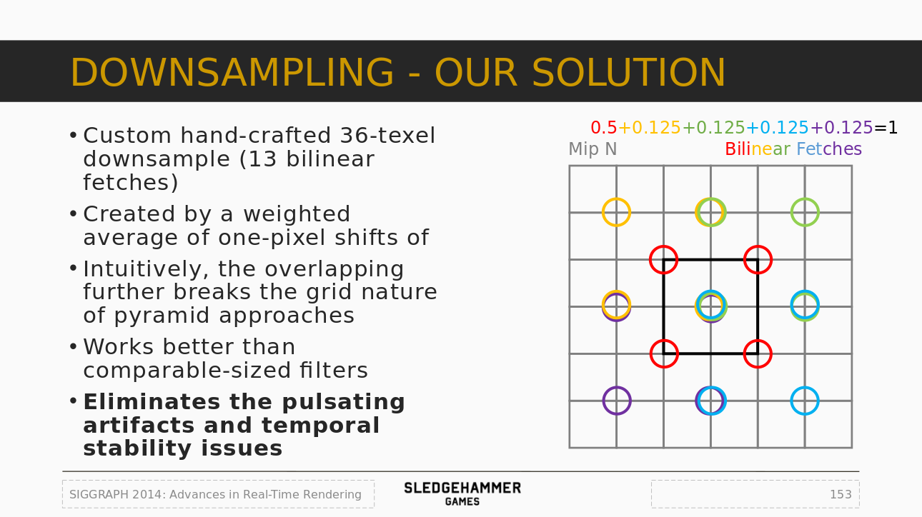
So let's make our own downsample pass based on this method:
TODO_SHADER_DOWNSAMPLE
    // Downsample shader
    class FDownsamplePS : public FGlobalShader
    {
        public:
            DECLARE_GLOBAL_SHADER(FDownsamplePS);
            SHADER_USE_PARAMETER_STRUCT(FDownsamplePS, FGlobalShader);

            BEGIN_SHADER_PARAMETER_STRUCT(FParameters, )
                SHADER_PARAMETER_STRUCT_INCLUDE(FCustomLensFlarePassParameters, Pass)
                SHADER_PARAMETER_SAMPLER(SamplerState, InputSampler)
                SHADER_PARAMETER(FVector2D, InputSize)
                SHADER_PARAMETER(float, ThresholdLevel)
                SHADER_PARAMETER(float, ThresholdRange)
            END_SHADER_PARAMETER_STRUCT()

            static bool ShouldCompilePermutation(const FGlobalShaderPermutationParameters& Parameters)
            {
                return IsFeatureLevelSupported(Parameters.Platform, ERHIFeatureLevel::SM5);
            }
    };
    IMPLEMENT_GLOBAL_SHADER(FDownsamplePS, "/CustomShaders/DownsampleThreshold.usf", "DownsampleThresholdPS", SF_Pixel);
DownsampleThreshold.usf
#include "Shared.ush"

float2 InputSize;
float ThresholdLevel;
float ThresholdRange;

void DownsampleThresholdPS(
    in noperspective float4 UVAndScreenPos : TEXCOORD0,
    out float3 OutColor : SV_Target0 )
{
    float2 InPixelSize = 1.0f / InputSize;
    float2 UV = UVAndScreenPos.xy;
    float3 Color = float3( 0.0f, 0.0f ,0.0f );

    // 4 central samples
    float2 CenterUV_1 = UV + InPixelSize * float2(-1.0f, 1.0f);
    float2 CenterUV_2 = UV + InPixelSize * float2( 1.0f, 1.0f);
    float2 CenterUV_3 = UV + InPixelSize * float2(-1.0f,-1.0f);
    float2 CenterUV_4 = UV + InPixelSize * float2( 1.0f,-1.0f);

    Color += Texture2DSample(InputTexture, InputSampler, CenterUV_1 ).rgb;
    Color += Texture2DSample(InputTexture, InputSampler, CenterUV_2 ).rgb;
    Color += Texture2DSample(InputTexture, InputSampler, CenterUV_3 ).rgb;
    Color += Texture2DSample(InputTexture, InputSampler, CenterUV_4 ).rgb;

    OutColor.rgb = (Color / 4.0f) * 0.5f;

    // 3 row samples
    Color = float3( 0.0f, 0.0f ,0.0f );

    float2 RowUV_1 = UV + InPixelSize * float2(-2.0f, 2.0f);
    float2 RowUV_2 = UV + InPixelSize * float2( 0.0f, 2.0f);
    float2 RowUV_3 = UV + InPixelSize * float2( 2.0f, 2.0f);

    float2 RowUV_4 = UV + InPixelSize * float2(-2.0f, 0.0f);
    float2 RowUV_5 = UV + InPixelSize * float2( 0.0f, 0.0f);
    float2 RowUV_6 = UV + InPixelSize * float2( 2.0f, 0.0f);

    float2 RowUV_7 = UV + InPixelSize * float2(-2.0f,-2.0f);
    float2 RowUV_8 = UV + InPixelSize * float2( 0.0f,-2.0f);
    float2 RowUV_9 = UV + InPixelSize * float2( 2.0f,-2.0f);

    Color += Texture2DSample(InputTexture, InputSampler, RowUV_1 ).rgb;
    Color += Texture2DSample(InputTexture, InputSampler, RowUV_2 ).rgb;
    Color += Texture2DSample(InputTexture, InputSampler, RowUV_3 ).rgb;

    Color += Texture2DSample(InputTexture, InputSampler, RowUV_4 ).rgb;
    Color += Texture2DSample(InputTexture, InputSampler, RowUV_5 ).rgb;
    Color += Texture2DSample(InputTexture, InputSampler, RowUV_6 ).rgb;

    Color += Texture2DSample(InputTexture, InputSampler, RowUV_7 ).rgb;
    Color += Texture2DSample(InputTexture, InputSampler, RowUV_8 ).rgb;
    Color += Texture2DSample(InputTexture, InputSampler, RowUV_9 ).rgb;

    OutColor.rgb += (Color / 9.0f) * 0.5f;

    // Threshold
    float Luminance = dot(OutColor.rgb, 1);
    float ThresholdScale = saturate( (Luminance - ThresholdLevel) / ThresholdRange );

    OutColor.rgb *= ThresholdScale;
}
As you can see here, first is the 13 samples (with the corresponding weights) then is the threshold which works by specify a level and a range for the fade in/out. The threshold is applied based on the pixel luminance which is computed via a dot product.
Now we just need to add the C++ code to run that shader:
TODO_THRESHOLD
    RDG_EVENT_SCOPE(GraphBuilder, "ThresholdPass");

    FRDGTextureRef OutputTexture = nullptr;

    FIntRect Viewport = View.ViewRect;
    FIntRect Viewport2 = FIntRect( 0, 0,
        View.ViewRect.Width() / 2,
        View.ViewRect.Height() / 2
    );
    FIntRect Viewport4 = FIntRect( 0, 0,
        View.ViewRect.Width() / 4,
        View.ViewRect.Height() / 4
    );
Since we are inside the RenderThreshold() function we can take the opportunity to add a dedicated event for profiling performances later. Then we setup the buffer that will be returned from the function and finally we set a few FIntRect as size reference for the intermediate buffer we are gonna build and render.
    {
        const FString PassName("LensFlareDownsample");

        // Build texture
        FRDGTextureDesc Description = InputTexture->Desc;
        Description.Reset();
        Description.Extent  = Viewport4.Size();
        Description.Format  = PF_FloatRGB;
        Description.ClearValue = FClearValueBinding(FLinearColor::Black);
        FRDGTextureRef Texture = GraphBuilder.CreateTexture(Description, *PassName);

        // Render shader
        TShaderMapRef<FCustomScreenPassVS> VertexShader(View.ShaderMap);
        TShaderMapRef<FDownsamplePS> PixelShader(View.ShaderMap);

        FDownsamplePS::FParameters* PassParameters = GraphBuilder.AllocParameters<FDownsamplePS::FParameters>();
        PassParameters->Pass.InputTexture       = InputTexture;
        PassParameters->Pass.RenderTargets[0]   = FRenderTargetBinding(Texture, ERenderTargetLoadAction::ENoAction);
        PassParameters->InputSampler            = BilinearClampSampler;
        PassParameters->InputSize               = FVector2D( Viewport2.Size() );
        PassParameters->ThresholdLevel          = PostProcessAsset->ThresholdLevel;
        PassParameters->ThresholdRange          = PostProcessAsset->ThresholdRange;

        DrawShaderPass(
            GraphBuilder,
            PassName,
            PassParameters,
            VertexShader,
            PixelShader,
            ClearBlendState,
            Viewport4
        );

        OutputTexture = Texture;
    }
Very similar setup to the rescale pass, which we are gonna see for the other rendering pass too. There is not much new to say here other than paying attention to a few little details:
You can notice that the parameters value are retrieved from the PostProcessAsset that we referenced earlier in the code.
Now that we have downsample pass, we can add the blur:
TODO_THRESHOLD_BLUR
    {
        OutputTexture = RenderBlur(
            GraphBuilder,
            OutputTexture,
            View,
            Viewport2,
            1
        );
    }

    return OutputTexture;

} // End of RenderThreshold()
The details on how this function works is in the next step.
Notice here the argument 1 passed to the function, this means only one pass of blur is performed. Since additional passes are expensive, and given we already did a custom downsample pass, blurring further isn't needed.
I spent a long time trying out different blur methods:
I ended up choosing the Dual Kawase method. It is an improvement over the original Kawase method that emulates a gaussian blur while remaining very fast to compute. The name of the method comes from Masaki Kawase who presented it at GDC (Game Developers Conference) initially.
In a few words, this blur method works by doing multiple passes where each pixel samples its neighbors. The blur strength therefore comes from the number of passes performed:
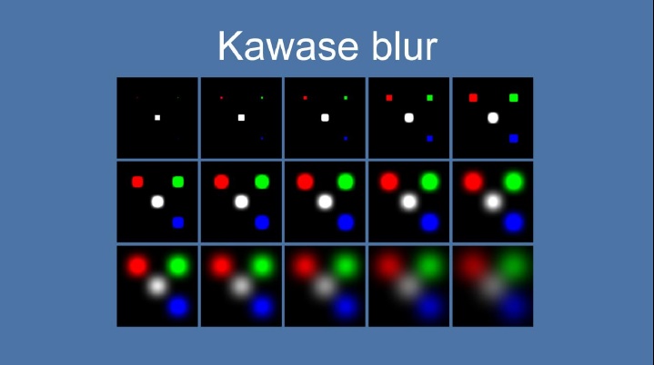
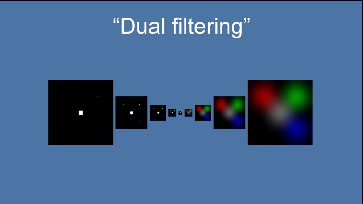
The dual version improve that process by taking advantage of the GPU native bilinear sampling: instead of keeping the buffer at the same size, each pass downsample the previous results. Then in the middle the opposite is done with upsampling passes. The down and then up process allow to take advantage of bilinear interpolation when reading pixel to process a lot more information at once.
This means that we can reduce the number of total passes needed and improve the fillrate by processing lower resolutions:
Because we are going to re-use this blur method a few times, I ended up moving the blur process into its own function RenderBlur():
TODO_BLUR
FRDGTextureRef UPostProcessSubsystem::RenderBlur(
        FRDGBuilder& GraphBuilder,
        FRDGTextureRef InputTexture,
        const FViewInfo& View,
        const FIntRect& Viewport,
        int BlurSteps
    )
{
    // Shader setup
    TShaderMapRef<FCustomScreenPassVS>  VertexShader(View.ShaderMap);
    TShaderMapRef<FKawaseBlurDownPS>    PixelShaderDown(View.ShaderMap);
    TShaderMapRef<FKawaseBlurUpPS>      PixelShaderUp(View.ShaderMap);

    // Data setup
    FRDGTextureRef PreviousBuffer = InputTexture;
    const FRDGTextureDesc& InputDescription = InputTexture->Desc;

    const FString PassDownName  = TEXT("Down");
    const FString PassUpName    = TEXT("Up");
    const int32 ArraySize = BlurSteps * 2;

    // Viewport resolutions
    // Could have been a bit more clever and avoid duplicate
    // sizes for upscale passes but heh... it works.
    int32 Divider = 2;
    TArray<FIntRect> Viewports;
    for( int32 i = 0; i < ArraySize; i++ )
    {
        FIntRect NewRect = FIntRect(
            0,
            0,
            Viewport.Width() / Divider,
            Viewport.Height() / Divider
        );

        Viewports.Add( NewRect );

        if( i < (BlurSteps - 1) )
        {
            Divider *= 2;
        }
        else
        {
            Divider /= 2;
        }
    }

[...]
The blur function starts with various preparations. Since the process downsample then upsample the input buffer when need different buffer sizes. The loop here basically generate these sizes based on the number of passes and the resolution that was based in the arguments.
BlurSteps is the input argument that defines how many down then up passes should be done. Calling the function with 1 therefore means one down and one up (so two passes in total).
Next is the rendering loop:
    // Render
    for( int32 i = 0; i < ArraySize; i++ )
    {
        // Build texture
        FRDGTextureDesc BlurDesc = InputDescription;
        BlurDesc.Reset();
        BlurDesc.Extent = Viewports[i].Size();
        BlurDesc.Format = PF_FloatRGB;
        BlurDesc.NumMips = 1;
        BlurDesc.ClearValue = FClearValueBinding(FLinearColor::Transparent);

        FVector2D ViewportResolution = FVector2D(
            Viewports[i].Width(),
            Viewports[i].Height()
        );

        const FString PassName =
            FString("KawaseBlur")
            +  FString::Printf( TEXT("_%i_"), i )
            +  ( (i < BlurSteps) ? PassDownName : PassUpName )
            +  FString::Printf( TEXT("_%ix%i"), Viewports[i].Width(), Viewports[i].Height() );

        FRDGTextureRef Buffer = GraphBuilder.CreateTexture(BlurDesc, *PassName);

        // Render shader
        if( i < BlurSteps )
        {
            FKawaseBlurDownPS::FParameters* PassDownParameters = GraphBuilder.AllocParameters<FKawaseBlurDownPS::FParameters>();
            PassDownParameters->Pass.InputTexture       = PreviousBuffer;
            PassDownParameters->Pass.RenderTargets[0]   = FRenderTargetBinding(Buffer, ERenderTargetLoadAction::ENoAction);
            PassDownParameters->InputSampler            = BilinearClampSampler;
            PassDownParameters->BufferSize              = ViewportResolution;

            DrawShaderPass(
                GraphBuilder,
                PassName,
                PassDownParameters,
                VertexShader,
                PixelShaderDown,
                ClearBlendState,
                Viewports[i]
            );
        }
        else
        {
            FKawaseBlurUpPS::FParameters* PassUpParameters = GraphBuilder.AllocParameters<FKawaseBlurUpPS::FParameters>();
            PassUpParameters->Pass.InputTexture         = PreviousBuffer;
            PassUpParameters->Pass.RenderTargets[0]     = FRenderTargetBinding(Buffer, ERenderTargetLoadAction::ENoAction);
            PassUpParameters->InputSampler              = BilinearClampSampler;
            PassUpParameters->BufferSize                = ViewportResolution;

            DrawShaderPass(
                GraphBuilder,
                PassName,
                PassUpParameters,
                VertexShader,
                PixelShaderUp,
                ClearBlendState,
                Viewports[i]
            );
        }

        PreviousBuffer = Buffer;
    }

    return PreviousBuffer;
RDG doesn't allow to re-use shader parameters, this is why each pass use AllocParameters() to build new parameters for each rendering call.
Now that we have the rendering code, let's setup the shader:
TODO_SHADER_KAWASE
    // Blur shader (use Dual Kawase method)
    class FKawaseBlurDownPS : public FGlobalShader
    {
        public:
            DECLARE_GLOBAL_SHADER(FKawaseBlurDownPS);
            SHADER_USE_PARAMETER_STRUCT(FKawaseBlurDownPS, FGlobalShader);

            BEGIN_SHADER_PARAMETER_STRUCT(FParameters, )
                SHADER_PARAMETER_STRUCT_INCLUDE(FCustomLensFlarePassParameters, Pass)
                SHADER_PARAMETER_SAMPLER(SamplerState, InputSampler)
                SHADER_PARAMETER(FVector2D, BufferSize)
            END_SHADER_PARAMETER_STRUCT()

            static bool ShouldCompilePermutation(const FGlobalShaderPermutationParameters& Parameters)
            {
                return IsFeatureLevelSupported(Parameters.Platform, ERHIFeatureLevel::SM5);
            }
    };
    class FKawaseBlurUpPS : public FGlobalShader
    {
        public:
            DECLARE_GLOBAL_SHADER(FKawaseBlurUpPS);
            SHADER_USE_PARAMETER_STRUCT(FKawaseBlurUpPS, FGlobalShader);

            BEGIN_SHADER_PARAMETER_STRUCT(FParameters, )
                SHADER_PARAMETER_STRUCT_INCLUDE(FCustomLensFlarePassParameters, Pass)
                SHADER_PARAMETER_SAMPLER(SamplerState, InputSampler)
                SHADER_PARAMETER(FVector2D, BufferSize)
            END_SHADER_PARAMETER_STRUCT()

            static bool ShouldCompilePermutation(const FGlobalShaderPermutationParameters& Parameters)
            {
                return IsFeatureLevelSupported(Parameters.Platform, ERHIFeatureLevel::SM5);
            }
    };
    IMPLEMENT_GLOBAL_SHADER(FKawaseBlurDownPS, "/CustomShaders/DualKawaseBlur.usf", "KawaseBlurDownsamplePS", SF_Pixel);
    IMPLEMENT_GLOBAL_SHADER(FKawaseBlurUpPS, "/CustomShaders/DualKawaseBlur.usf", "KawaseBlurUpsamplePS", SF_Pixel);
DualKawaseBlur.usf
#include "Shared.ush"

float2 BufferSize;

void KawaseBlurDownsamplePS(
    in noperspective float4 UVAndScreenPos : TEXCOORD0,
    out float4 OutColor : SV_Target0 )
{
    float2 UV = UVAndScreenPos.xy;
    float2 HalfPixel = (1.0f / BufferSize) * 0.5f;

    float2 DirDiag1 = float2( -HalfPixel.x,  HalfPixel.y ); // Top left
    float2 DirDiag2 = float2(  HalfPixel.x,  HalfPixel.y ); // Top right
    float2 DirDiag3 = float2(  HalfPixel.x, -HalfPixel.y ); // Bottom right
    float2 DirDiag4 = float2( -HalfPixel.x, -HalfPixel.y ); // Bottom left

    float3 Color = Texture2DSample(InputTexture, InputSampler, UV ).rgb * 4.0f;
    Color += Texture2DSample(InputTexture, InputSampler, UV + DirDiag1 ).rgb;
    Color += Texture2DSample(InputTexture, InputSampler, UV + DirDiag2 ).rgb;
    Color += Texture2DSample(InputTexture, InputSampler, UV + DirDiag3 ).rgb;
    Color += Texture2DSample(InputTexture, InputSampler, UV + DirDiag4 ).rgb;

    OutColor.rgb = Color / 8.0f;
    OutColor.a = 0.0f;
}

void KawaseBlurUpsamplePS(
    in noperspective float4 UVAndScreenPos : TEXCOORD0,
    out float4 OutColor : SV_Target0 )
{
    float2 UV = UVAndScreenPos.xy;
    float2 HalfPixel = (1.0f / BufferSize) * 0.5f;

    float2 DirDiag1 = float2( -HalfPixel.x,  HalfPixel.y ); // Top left
    float2 DirDiag2 = float2(  HalfPixel.x,  HalfPixel.y ); // Top right
    float2 DirDiag3 = float2(  HalfPixel.x, -HalfPixel.y ); // Bottom right
    float2 DirDiag4 = float2( -HalfPixel.x, -HalfPixel.y ); // Bottom left
    float2 DirAxis1 = float2( -HalfPixel.x,  0.0f );        // Left
    float2 DirAxis2 = float2(  HalfPixel.x,  0.0f );        // Right
    float2 DirAxis3 = float2( 0.0f,  HalfPixel.y );         // Top
    float2 DirAxis4 = float2( 0.0f, -HalfPixel.y );         // Bottom

    float3 Color = float3( 0.0f, 0.0f, 0.0f );

    Color += Texture2DSample(InputTexture, InputSampler, UV + DirDiag1 ).rgb;
    Color += Texture2DSample(InputTexture, InputSampler, UV + DirDiag2 ).rgb;
    Color += Texture2DSample(InputTexture, InputSampler, UV + DirDiag3 ).rgb;
    Color += Texture2DSample(InputTexture, InputSampler, UV + DirDiag4 ).rgb;

    Color += Texture2DSample(InputTexture, InputSampler, UV + DirAxis1 ).rgb * 2.0f;
    Color += Texture2DSample(InputTexture, InputSampler, UV + DirAxis2 ).rgb * 2.0f;
    Color += Texture2DSample(InputTexture, InputSampler, UV + DirAxis3 ).rgb * 2.0f;
    Color += Texture2DSample(InputTexture, InputSampler, UV + DirAxis4 ).rgb * 2.0f;

    OutColor.rgb = Color / 12.0f;
    OutColor.a = 0.0f;
}
The downsample function performs four samples here in four directions (axis aligned) at a distance of half a pixel (of the given buffer resolution). The upsample function does height samples because it includes diagonals directions and applies different weights.
Something to be aware of is that since the Kawase blur works by reading neighbors pixels, it means that for two identical images but at different resolution, one of them will need more passes to reach the same level of blur visually.
This means that in various passes I used a specific size that fits well a 1080p resolution, but if your game render above (say 4K) you may need to adjust the intensity by increasing the number of passes to reach the same visual parity.
We can now do the first visual pass and build up the ghosts. The idea is actually pretty simple and divided into a few steps:
All of this will be done inside the RenderFlare() function.
TODO_SHADER_CHROMA
    // Chromatic shift shader
    class FLensFlareChromaPS : public FGlobalShader
    {
        public:
            DECLARE_GLOBAL_SHADER(FLensFlareChromaPS);
            SHADER_USE_PARAMETER_STRUCT(FLensFlareChromaPS, FGlobalShader);

            BEGIN_SHADER_PARAMETER_STRUCT(FParameters, )
                SHADER_PARAMETER_STRUCT_INCLUDE(FCustomLensFlarePassParameters, Pass)
                SHADER_PARAMETER_SAMPLER(SamplerState, InputSampler)
                SHADER_PARAMETER(float, ChromaShift)
            END_SHADER_PARAMETER_STRUCT()

            static bool ShouldCompilePermutation(const FGlobalShaderPermutationParameters& Parameters)
            {
                return IsFeatureLevelSupported(Parameters.Platform, ERHIFeatureLevel::SM5);
            }
    };
    IMPLEMENT_GLOBAL_SHADER(FLensFlareChromaPS, "/CustomShaders/Chroma.usf", "ChromaPS", SF_Pixel);
Chroma.usf
#include "Shared.ush"

float ChromaShift;

void ChromaPS(
    in noperspective float4 UVAndScreenPos : TEXCOORD0,
    out float3 OutColor : SV_Target0)
{
    float2 UV = UVAndScreenPos.xy;
    const float2 CenterPoint = float2( 0.5f, 0.5f );
    float2 UVr = (UV - CenterPoint) * (1.0f + ChromaShift) + CenterPoint;
    float2 UVb = (UV - CenterPoint) * (1.0f - ChromaShift) + CenterPoint;

    OutColor.r = Texture2DSample(InputTexture, InputSampler, UVr ).r;
    OutColor.g = Texture2DSample(InputTexture, InputSampler, UV  ).g;
    OutColor.b = Texture2DSample(InputTexture, InputSampler, UVb ).b;
}
TODO_FLARE_CHROMA
    RDG_EVENT_SCOPE(GraphBuilder, "FlarePass");

    FRDGTextureRef OutputTexture = nullptr;

    FIntRect Viewport = View.ViewRect;
    FIntRect Viewport2 = FIntRect( 0, 0,
        View.ViewRect.Width() / 2,
        View.ViewRect.Height() / 2
    );
    FIntRect Viewport4 = FIntRect( 0, 0,
        View.ViewRect.Width() / 4,
        View.ViewRect.Height() / 4
    );
Like in the threshold function, we have to setup a few things before starting to render things. Then we can perform the chromatic shift pass:
    FRDGTextureRef ChromaTexture = nullptr;

    {
        const FString PassName("LensFlareChromaGhost");

        // Build buffer
        FRDGTextureDesc Description = InputTexture->Desc;
        Description.Reset();
        Description.Extent  = Viewport2.Size();
        Description.Format  = PF_FloatRGB;
        Description.ClearValue = FClearValueBinding(FLinearColor::Black);
        ChromaTexture = GraphBuilder.CreateTexture(Description, *PassName);

        // Shader parameters
        TShaderMapRef<FCustomScreenPassVS> VertexShader(View.ShaderMap);
        TShaderMapRef<FLensFlareChromaPS> PixelShader(View.ShaderMap);

        FLensFlareChromaPS::FParameters* PassParameters = GraphBuilder.AllocParameters<FLensFlareChromaPS::FParameters>();
        PassParameters->Pass.InputTexture       = InputTexture;
        PassParameters->Pass.RenderTargets[0]   = FRenderTargetBinding(ChromaTexture, ERenderTargetLoadAction::ENoAction);
        PassParameters->InputSampler            = BilinearBorderSampler;
        PassParameters->ChromaShift             = PostProcessAsset->GhostChromaShift;

        // Render
        DrawShaderPass(
            GraphBuilder,
            PassName,
            PassParameters,
            VertexShader,
            PixelShader,
            ClearBlendState,
            Viewport2
        );
    }
Notice how the variable ChromaTexture sits outside the scope. Since we aren't chaining the renders this time, we need an additional buffer to combine things later.
Now that the chromatic shift is done, we can perform the loop to draw it in sequence and create the ghost effect.
The shader is rather simple since it's a basic loop. The only peculiar thing is that it uses a few custom masks in order to hide the ghosts at specific location on the screen.
TODO_SHADER_GHOSTS
    // Ghost shader
    class FLensFlareGhostsPS : public FGlobalShader
    {
        public:
            DECLARE_GLOBAL_SHADER(FLensFlareGhostsPS);
            SHADER_USE_PARAMETER_STRUCT(FLensFlareGhostsPS, FGlobalShader);

            BEGIN_SHADER_PARAMETER_STRUCT(FParameters, )
                SHADER_PARAMETER_STRUCT_INCLUDE(FCustomLensFlarePassParameters, Pass)
                SHADER_PARAMETER_SAMPLER(SamplerState, InputSampler)
                SHADER_PARAMETER_ARRAY(FVector4, GhostColors, [8])
                SHADER_PARAMETER_ARRAY(float, GhostScales, [8])
                SHADER_PARAMETER(float, Intensity)
            END_SHADER_PARAMETER_STRUCT()

            static bool ShouldCompilePermutation(const FGlobalShaderPermutationParameters& Parameters)
            {
                return IsFeatureLevelSupported(Parameters.Platform, ERHIFeatureLevel::SM5);
            }
    };
    IMPLEMENT_GLOBAL_SHADER(FLensFlareGhostsPS, "/CustomShaders/Ghosts.usf", "GhostsPS", SF_Pixel);
Note here a new type of parameters with SHADER_PARAMETER_ARRAY, this macro allows to define an array parameter for the shader. This macro takes three arguments: the data type, the variable name, and the size of the array (specified between square brackets).
In this case the number of ghosts to draw is fixed (height are defined in the Data Asset).
Ghosts.usf
#include "Shared.ush"

float4 GhostColors[8];
float GhostScales[8];
float Intensity;

void GhostsPS(
    in noperspective float4 UVAndScreenPos : TEXCOORD0,
    out float4 OutColor : SV_Target0 )
{
    float2 UV = UVAndScreenPos.xy;
    float3 Color = float3( 0.0f, 0.0f, 0.0f );

    for( int i = 0; i < 8; i++ )
    {
        // Skip ghost if size is basically 0
        if( abs(GhostColors[i].a * GhostScales[i]) > 0.0001f )
        {
            float2 NewUV = (UV - 0.5f) * GhostScales[i];

            // Local mask
            float DistanceMask = 1.0f - distance( float2(0.0f, 0.0f), NewUV );
            float Mask  = smoothstep( 0.5f, 0.9f, DistanceMask );
            float Mask2 = smoothstep( 0.75f, 1.0f, DistanceMask ) * 0.95f + 0.05f;

            Color += Texture2DSample(InputTexture, InputSampler, NewUV + 0.5f ).rgb
                    * GhostColors[i].rgb
                    * GhostColors[i].a
                    * Mask * Mask2;
        }
    }

    float2 ScreenPos = UVAndScreenPos.zw;
    float ScreenborderMask = DiscMask(ScreenPos * 0.9f);

    OutColor.rgb = Color * ScreenborderMask * Intensity;

    OutColor.a = 0;
}
Below is a comparison of what the masking operations are doing. The local mask is used to make the ghosts bright in their middle but faded on their outside border. This an artistic choice I made so that looking at light source directly would feel bright and looking away would be less intrusive. Then the screen border mask simply ensure that there is no seam visible that would make the effect ugly.
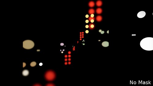
(No masking at all)
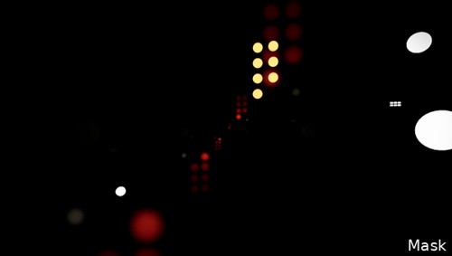
(Local masking, applied in the loop on each ghost)
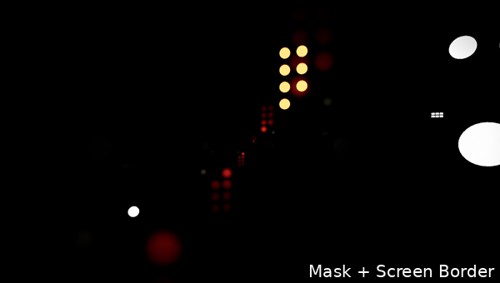
(Masking at the borders of the screen)
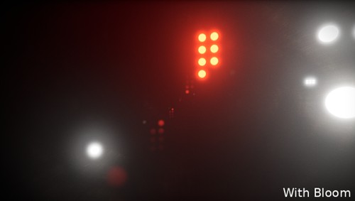
(Combined with bloom)
TODO_FLARE_GHOSTS
    {
        const FString PassName("LensFlareGhosts");

        // Build buffer
        FRDGTextureDesc Description = InputTexture->Desc;
        Description.Reset();
        Description.Extent  = Viewport2.Size();
        Description.Format  = PF_FloatRGB;
        Description.ClearValue = FClearValueBinding(FLinearColor::Transparent);
        FRDGTextureRef Texture = GraphBuilder.CreateTexture(Description, *PassName);

        // Shader parameters
        TShaderMapRef<FCustomScreenPassVS> VertexShader(View.ShaderMap);
        TShaderMapRef<FLensFlareGhostsPS> PixelShader(View.ShaderMap);

        FLensFlareGhostsPS::FParameters* PassParameters = GraphBuilder.AllocParameters<FLensFlareGhostsPS::FParameters>();
        PassParameters->Pass.InputTexture       = ChromaTexture;
        PassParameters->Pass.RenderTargets[0]   = FRenderTargetBinding(Texture, ERenderTargetLoadAction::ENoAction);
        PassParameters->InputSampler            = BilinearBorderSampler;
        PassParameters->Intensity               = PostProcessAsset->GhostIntensity;

        PassParameters->GhostColors[0] = PostProcessAsset->Ghost1.Color;
        PassParameters->GhostColors[1] = PostProcessAsset->Ghost2.Color;
        PassParameters->GhostColors[2] = PostProcessAsset->Ghost3.Color;
        PassParameters->GhostColors[3] = PostProcessAsset->Ghost4.Color;
        PassParameters->GhostColors[4] = PostProcessAsset->Ghost5.Color;
        PassParameters->GhostColors[5] = PostProcessAsset->Ghost6.Color;
        PassParameters->GhostColors[6] = PostProcessAsset->Ghost7.Color;
        PassParameters->GhostColors[7] = PostProcessAsset->Ghost8.Color;

        PassParameters->GhostScales[0] = PostProcessAsset->Ghost1.Scale;
        PassParameters->GhostScales[1] = PostProcessAsset->Ghost2.Scale;
        PassParameters->GhostScales[2] = PostProcessAsset->Ghost3.Scale;
        PassParameters->GhostScales[3] = PostProcessAsset->Ghost4.Scale;
        PassParameters->GhostScales[4] = PostProcessAsset->Ghost5.Scale;
        PassParameters->GhostScales[5] = PostProcessAsset->Ghost6.Scale;
        PassParameters->GhostScales[6] = PostProcessAsset->Ghost7.Scale;
        PassParameters->GhostScales[7] = PostProcessAsset->Ghost8.Scale;

        // Render
        DrawShaderPass(
            GraphBuilder,
            PassName,
            PassParameters,
            VertexShader,
            PixelShader,
            ClearBlendState,
            Viewport2
        );

        OutputTexture = Texture;
    }
Nothing special once again apart from the way the array parameters are assigned. It's a basic static array, so it would be possible to build a for loop to assign values. This is not the case here because the data asset doesn't use an array (to avoid this bug).
The halo effect is based on John Chapman's article which I briefly mentioned when talking about Cyberpunk 2077 above:
Roughly the idea is to build a direction vector to distort the UV coordinates. This push bright light sitting at the center of the screen toward the edges.
I tweaked this idea further by distorting the UVs with a fish eye effects which pushes information even further toward the screen edges. The reason why is because I wanted to get a very thin halo most of the time and avoid too much overlapping with the ghosts we added previously.
Some example of regular halo (left) vs fisheye halo (right):
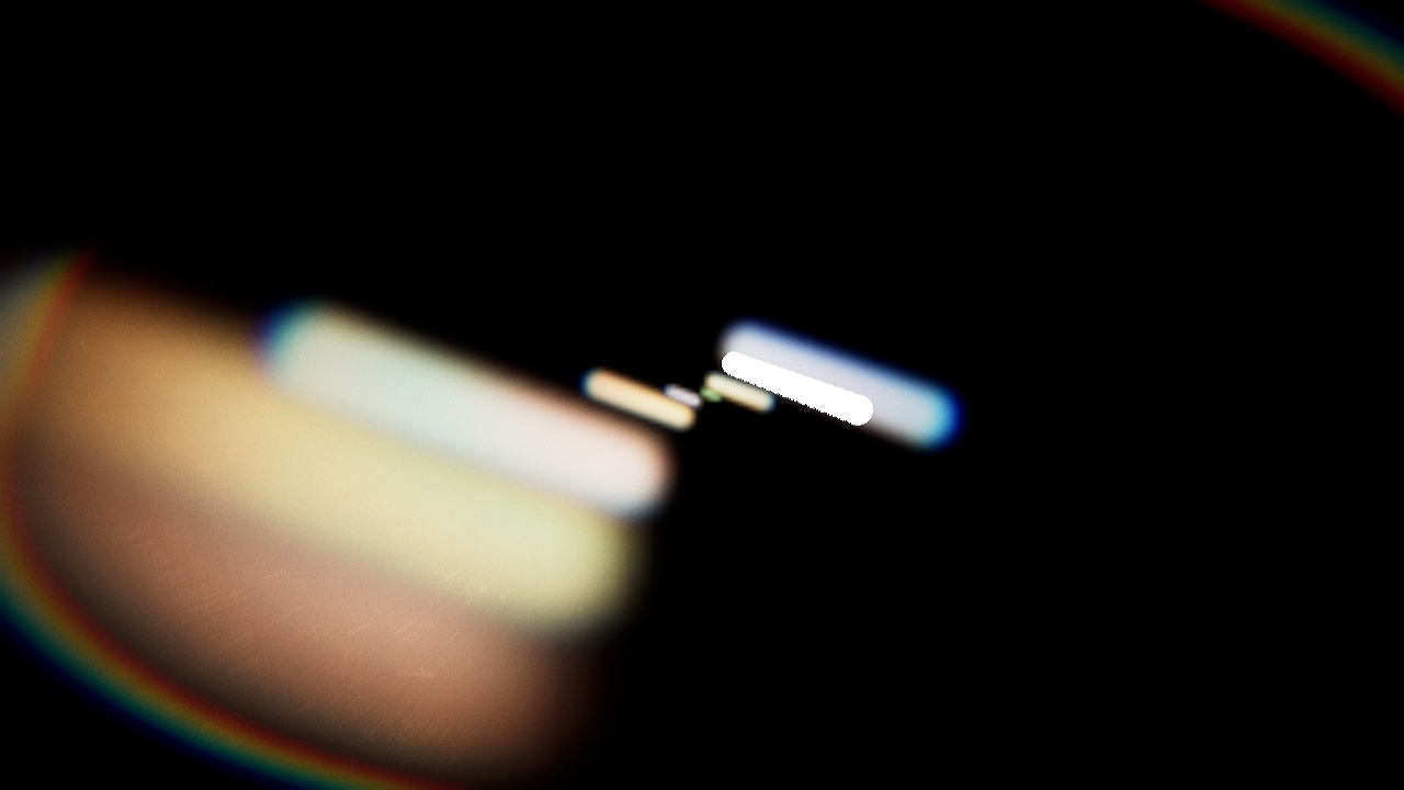
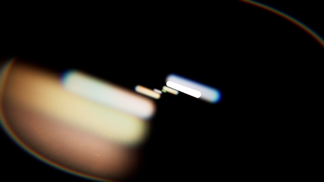
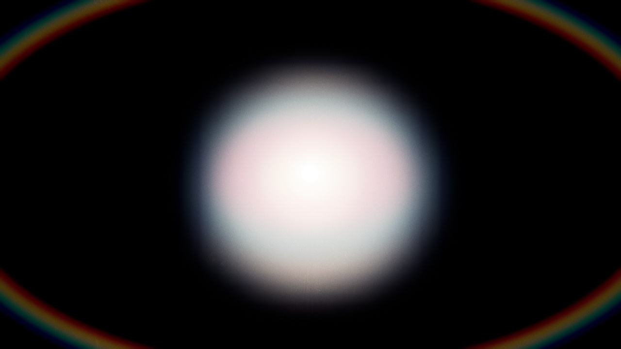
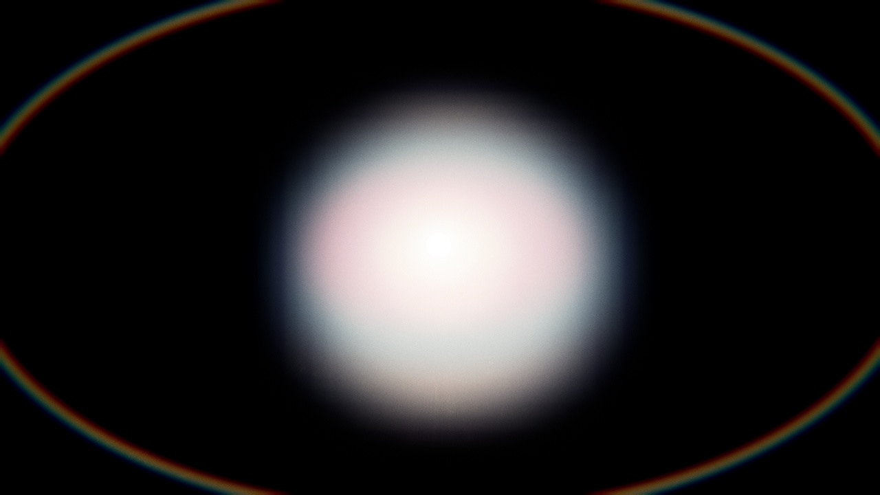
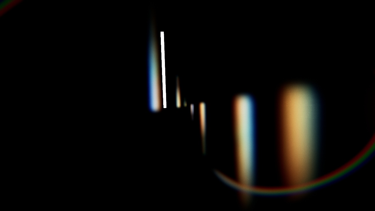
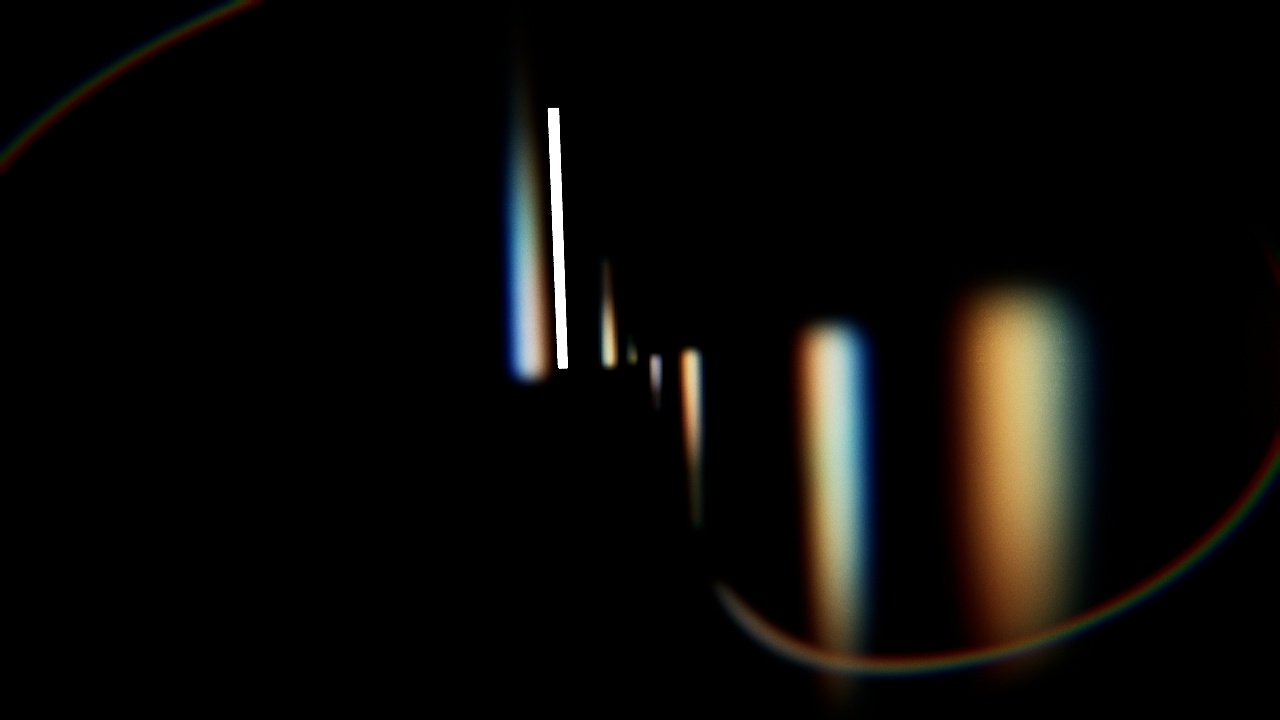
TODO_SHADER_HALO
    class FLensFlareHaloPS : public FGlobalShader
    {
        public:
            DECLARE_GLOBAL_SHADER(FLensFlareHaloPS);
            SHADER_USE_PARAMETER_STRUCT(FLensFlareHaloPS, FGlobalShader);

            BEGIN_SHADER_PARAMETER_STRUCT(FParameters, )
                SHADER_PARAMETER_STRUCT_INCLUDE(FCustomLensFlarePassParameters, Pass)
                SHADER_PARAMETER_SAMPLER(SamplerState, InputSampler)
                SHADER_PARAMETER(float, Width)
                SHADER_PARAMETER(float, Mask)
                SHADER_PARAMETER(float, Compression)
                SHADER_PARAMETER(float, Intensity)
                SHADER_PARAMETER(float, ChromaShift)
            END_SHADER_PARAMETER_STRUCT()

            static bool ShouldCompilePermutation(const FGlobalShaderPermutationParameters& Parameters)
            {
                return IsFeatureLevelSupported(Parameters.Platform, ERHIFeatureLevel::SM5);
            }
    };
    IMPLEMENT_GLOBAL_SHADER(FLensFlareHaloPS, "/CustomShaders/Halo.usf", "HaloPS", SF_Pixel);
Only note I would give here is that as you can see there is a few float parameters. It could be tempting to merge theme together as FVectors for example but it's actually not necessary as RDG do this kind of parameter grouping/batching automatically.
Halo.usf
#include "Shared.ush"

float2 FisheyeUV( float2 UV, float Compression, float Zoom )
{
    float2 NegPosUV = (2.0f * UV - 1.0f);

    float Scale = Compression * atan( 1.0f / Compression );
    float RadiusDistance = length(NegPosUV) * Scale;
    float RadiusDirection = Compression * tan( RadiusDistance / Compression ) * Zoom;
    float Phi = atan2( NegPosUV.y, NegPosUV.x );

    float2 NewUV = float2(  RadiusDirection * cos(Phi) + 1.0,
                            RadiusDirection * sin(Phi) + 1.0 );
    NewUV = NewUV / 2.0;

    return NewUV;
}

[...]
This Fisheye function that distort UVs is based on this shadertoy with slight adjustments to be able to easily scale the effect.
[...]

float Width;
float Mask;
float Compression;
float Intensity;
float ChromaShift;

void HaloPS(
    in noperspective float4 UVAndScreenPos : TEXCOORD0,
    out float3 OutColor : SV_Target0)
{
    const float2 CenterPoint = float2( 0.5f, 0.5f );

    // UVs
    float2 UV = UVAndScreenPos.xy;
    float2 FishUV = FisheyeUV( UV, Compression, 1.0f );

    // Distortion vector
    float2 HaloVector = normalize( CenterPoint - UV ) * Width;

    // Halo mask
    float HaloMask = distance( UV, CenterPoint );
    HaloMask = saturate(HaloMask * 2.0f);
    HaloMask = smoothstep( Mask, 1.0f, HaloMask );

    // Screen border mask
    float2 ScreenPos = UVAndScreenPos.zw;
    float ScreenborderMask = DiscMask(ScreenPos);
    ScreenborderMask *= DiscMask(ScreenPos * 0.8f);
    ScreenborderMask = ScreenborderMask * 0.95 + 0.05; // Scale range

    // Chroma offset
    float2 UVr = (FishUV - CenterPoint) * (1.0f + ChromaShift) + CenterPoint + HaloVector;
    float2 UVg = FishUV + HaloVector;
    float2 UVb = (FishUV - CenterPoint) * (1.0f - ChromaShift) + CenterPoint + HaloVector;

    // Sampling
    OutColor.r = Texture2DSample( InputTexture, InputSampler, UVr ).r;
    OutColor.g = Texture2DSample( InputTexture, InputSampler, UVg ).g;
    OutColor.b = Texture2DSample( InputTexture, InputSampler, UVb ).b;

    OutColor.rgb *= ScreenborderMask * HaloMask * Intensity;

}
Like mentioned above, all the work is done by altering the UV coordinates. The fish eye UVs are computed first, then the HaloVector compute a direction from the center of the screen. It gets added to the new UV coordinates when sampling happens.
Contrary to the Ghosts, the chroma effect is done in the same shader via three separate samples. At the end the result is masked out with a few custom masks to hide some artifacts. Note the DiscMask() function which is a function provided by Unreal shader system which allows to generate a radial/vignette type of masking. To avoid the mask flushing out too much colors, its range is scaled to avoid value that goes to pure black.
TODO_FLARE_HALO
    {
        // Render shader
        const FString PassName("LensFlareHalo");

        TShaderMapRef<FCustomScreenPassVS> VertexShader(View.ShaderMap);
        TShaderMapRef<FLensFlareHaloPS> PixelShader(View.ShaderMap);

        FLensFlareHaloPS::FParameters* PassParameters = GraphBuilder.AllocParameters<FLensFlareHaloPS::FParameters>();
        PassParameters->Pass.InputTexture       = InputTexture;
        PassParameters->Pass.RenderTargets[0]   = FRenderTargetBinding(OutputTexture, ERenderTargetLoadAction::ELoad);
        PassParameters->InputSampler            = BilinearBorderSampler;
        PassParameters->Intensity               = PostProcessAsset->HaloIntensity;
        PassParameters->Width                   = PostProcessAsset->HaloWidth;
        PassParameters->Mask                    = PostProcessAsset->HaloMask;
        PassParameters->Compression             = PostProcessAsset->HaloCompression;
        PassParameters->ChromaShift             = PostProcessAsset->HaloChromaShift;

        DrawShaderPass(
            GraphBuilder,
            PassName,
            PassParameters,
            VertexShader,
            PixelShader,
            AdditiveBlendState,
            Viewport2
        );
    }
This rendering pass is slightly different from the previous one we saw: this time we don't build a new buffer, instead we write into the previous one in additive mode which already contains the Ghosts.
It wouldn't make sense to to that into an intermediate buffer just to copy it back over the Ghosts afterward. So it's faster and cheaper to simply draw over the existing content. Since we are in additive more and lens-flares are lighting information, this works well.
Therefore, this is what the FRenderTargetBinding() use OutputTexture with the ERenderTargetLoadAction::ELoad and that DrawShaderPass() is called with AdditiveBlendState.
We are not yet done: because of the way the UVs are distorted, some artifacts or aliasing can very noticeable:
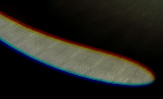
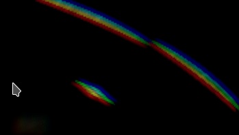
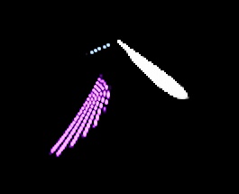
I tried several solutions to solve this issue (like generating mipmaps on the input buffer to get better interpolation) but didn't find anything better than simply blurring the final result. Blurring the Ghosts combined with the Halo buffer has also the advantage of fitting everything together.
To do so, we can simply call again the blur function (once again with a single pass):
    {
        OutputTexture = RenderBlur(
            GraphBuilder,
            OutputTexture,
            View,
            Viewport2,
            1
        );
    }

    return OutputTexture;

} // End of RenderFlare()
This pass is heavily inspired from Batman, because I found it to be very clever, fast, good enough and with plenty of artistic controls to produce interesting results.
Another method to generate glares is to perform several directional blurs from the input buffer and to combine them to create these light streak, like demonstrated by Masaki Kawase in this presentation.
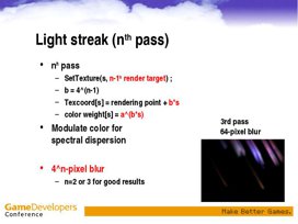
The reason why I didn't go with this method is that it is harder to control colors, sizes and that it requires a large amount of passes. Plus by the nature of the process, little details can easily be lost in the process.
I iterated a long time on it because it proved hard to get something both performant and good looking.
I initially built a version on the same idea as Unreal bokeh blur: draw an instanced and stretched quad for each pixel to build the star shape. Only one quad is drawn per pixel, therefore in order to make a star shape at least 3 quads are required (which once crossed give 6 branches). This is achieved by grouping pixels in two by two blocks, each block having 3 dedicated quads.
This proved the idea could work but performances still weren't good. There was some overhead in the way the quads were being emitted on the GPU which led to a high fixed cost even when nothing should be drawn. (Also it turned out a similar idea had been tried in the past).
So I went with a slightly different approach by splitting the process:
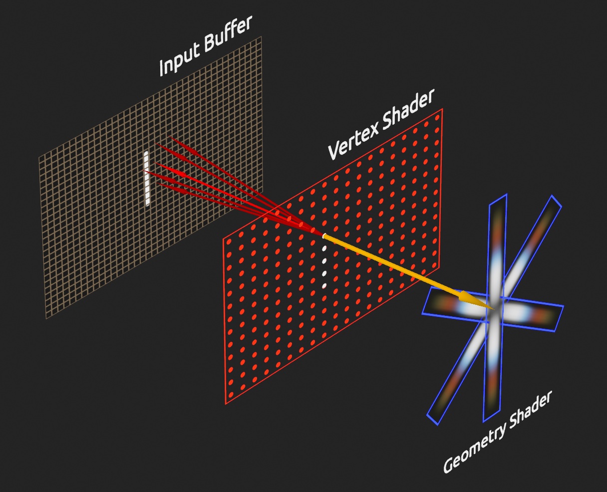
(The Pixel shader is combined with the Geometry shader in this schematic for readability)
Instead of rendering quads directly, we use points (one per group of four pixels).
In the Vertex shader multiple pixels are sampled around the point location. The results are combined and the luminance is computed. Then a geometry shader follow up and emit three quads if the previous luminance is high enough.
Nothing is rasterized if no point is deemed "valid" (aka bright enough). The base cost of emitting the points is very low. All the work is now within the Geometry shader and it can be easily skipped. The final cost now end-up being the overdraw when having lots of quads overlapping each other.
Here is the sampling pattern of each point:
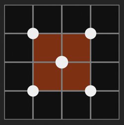
(Squares are pixels, dots are sampling positions)
Basically, for a block of two by two pixels, read the information at the center and at each corner of the block. Because we are reading pixels with bilinear interpolation we can aggregate lots of information. The pixel values are mixed with a more important weight at the center.
This pattern has the advantage of making transition and camera movement more stable. Otherwise the Glare effect would pulsate/flicker as seen in the Threshold pass.
After some trial and error I came up with this custom pattern which remains cheap (only 5 reading) while being good enough visually. I haven't found a way to stabilize further the effect without loosing too much information and luminosity.
Because we need three shaders for implementing the Glare effect (Vertex, Geometry and Pixel), it means this pass will be built a bit differently from the previous ones.
TODO_SHADER_GLARE
    // Glare shader pass
    class FLensFlareGlareVS : public FGlobalShader
    {
        public:
            DECLARE_GLOBAL_SHADER(FLensFlareGlareVS);
            SHADER_USE_PARAMETER_STRUCT(FLensFlareGlareVS, FGlobalShader);

            BEGIN_SHADER_PARAMETER_STRUCT(FParameters, )
                SHADER_PARAMETER_STRUCT_INCLUDE(FCustomLensFlarePassParameters, Pass)
                SHADER_PARAMETER_SAMPLER(SamplerState, InputSampler)
                SHADER_PARAMETER(FIntPoint, TileCount)
                SHADER_PARAMETER(FVector4, PixelSize)
                SHADER_PARAMETER(FVector2D, BufferSize)
            END_SHADER_PARAMETER_STRUCT()
    };
    class FLensFlareGlareGS : public FGlobalShader
    {
        public:
            DECLARE_GLOBAL_SHADER(FLensFlareGlareGS);
            SHADER_USE_PARAMETER_STRUCT(FLensFlareGlareGS, FGlobalShader);

            BEGIN_SHADER_PARAMETER_STRUCT(FParameters, )
                SHADER_PARAMETER(FVector4, PixelSize)
                SHADER_PARAMETER(FVector2D, BufferSize)
                SHADER_PARAMETER(FVector2D, BufferRatio)
                SHADER_PARAMETER(float, GlareIntensity)
                SHADER_PARAMETER(float, GlareDivider)
                SHADER_PARAMETER(FVector4, GlareTint)
                SHADER_PARAMETER_ARRAY(float, GlareScales, [3])
            END_SHADER_PARAMETER_STRUCT()
    };
    class FLensFlareGlarePS : public FGlobalShader
    {
        public:
            DECLARE_GLOBAL_SHADER(FLensFlareGlarePS);
            SHADER_USE_PARAMETER_STRUCT(FLensFlareGlarePS, FGlobalShader);

            BEGIN_SHADER_PARAMETER_STRUCT(FParameters, )
                SHADER_PARAMETER_SAMPLER(SamplerState, GlareSampler)
                SHADER_PARAMETER_TEXTURE(Texture2D, GlareTexture)
            END_SHADER_PARAMETER_STRUCT()

            static bool ShouldCompilePermutation(const FGlobalShaderPermutationParameters& Parameters)
            {
                return IsFeatureLevelSupported(Parameters.Platform, ERHIFeatureLevel::SM5);
            }
    };
    IMPLEMENT_GLOBAL_SHADER(FLensFlareGlareVS, "/CustomShaders/Glare.usf", "GlareVS", SF_Vertex);
    IMPLEMENT_GLOBAL_SHADER(FLensFlareGlareGS, "/CustomShaders/Glare.usf", "GlareGS", SF_Geometry);
    IMPLEMENT_GLOBAL_SHADER(FLensFlareGlarePS, "/CustomShaders/Glare.usf", "GlarePS", SF_Pixel);
Most of the shader setup here is similar to the previous ones we saw. There is a new macro we didn't see until now which is SHADER_PARAMETER_TEXTURE: it allows us to declare a generic texture to plug into the shader. Like you would do in regular materials in the content browser.
The texture we are gonna connect is the line mask from the data asset (visible in the geometry shader part of the schematic above).
Let's jump into the RenderGlare() function to add the rendering steps. I ill cover the shader themselves just after.
TODO_GLARE
FRDGTextureRef UPostProcessSubsystem::RenderGlare(
        FRDGBuilder& GraphBuilder,
        FRDGTextureRef InputTexture,
        FIntRect& InputRect,
        const FViewInfo& View
    )
{
    RDG_EVENT_SCOPE(GraphBuilder, "GlarePass");

    FRDGTextureRef OutputTexture = nullptr;

    FIntRect Viewport4 = FIntRect(
        0,
        0,
        View.ViewRect.Width() / 4,
        View.ViewRect.Height() / 4
    );

[...]
Let's continue with the actual rendering:
[...]

    // Only render the Glare if its intensity is different from 0
    if( PostProcessAsset->GlareIntensity > SMALL_NUMBER )
    {
        const FString PassName("LensFlareGlare");

        // This compute the number of point that will be drawn
        // Since we want one point for 2 by 2 pixel block we just
        // need to divide the resolution by two to get this value.
        FIntPoint TileCount = Viewport4.Size();
        TileCount.X = TileCount.X / 2;
        TileCount.Y = TileCount.Y / 2;
        int32 Amount = TileCount.X * TileCount.Y;

        // Compute the ratio between the width and height
        // to know how to adjust the scaling of the quads.
        // (This assume width is bigger than height.)
        FVector2D BufferRatio = FVector2D(
            float( Viewport4.Height() ) / float( Viewport4.Width() ),
            1.0f
        );

        // Build the buffer
        FRDGTextureDesc Description = InputTexture->Desc;
        Description.Reset();
        Description.Extent  = Viewport4.Size();
        Description.Format  = PF_FloatRGB;
        Description.ClearValue = FClearValueBinding(FLinearColor::Transparent);
        FRDGTextureRef GlareTexture = GraphBuilder.CreateTexture(Description, *PassName);

        // Setup a few other variables that will
        // be needed by the shaders.
        FVector4 PixelSize = FVector4(0,0,0,0);
        PixelSize.X = 1.0f / float( Viewport4.Width() );
        PixelSize.Y = 1.0f / float( Viewport4.Height() );
        PixelSize.Z = PixelSize.X;
        PixelSize.W = PixelSize.Y * -1.0f;

        FVector2D BufferSize = FVector2D( Description.Extent );
[...]
The rendering pass is inside an if block to easily discard its computation if the intensity is deemed too low. No need to render something that won't be visible in the end. Then we follow up with the setup of a few variables.
Like the comment mentions, the amount of points that will be drawn is driven by the resolution of the buffer in which we are gonna draw the quads. However since we want to draw only 1 point per 2 by 2 pixel blocks we divide the resolution in two.
Next is the shader parameters setup:
[...]

        // Setup shader
        FCustomLensFlarePassParameters* PassParameters = GraphBuilder.AllocParameters<FCustomLensFlarePassParameters>();
        PassParameters->InputTexture = InputTexture;
        PassParameters->RenderTargets[0] = FRenderTargetBinding(GlareTexture, ERenderTargetLoadAction::EClear);

        // Vertex shader
        FLensFlareGlareVS::FParameters VertexParameters;
        VertexParameters.Pass = *PassParameters;
        VertexParameters.InputSampler = BilinearBorderSampler;
        VertexParameters.TileCount = TileCount;
        VertexParameters.PixelSize = PixelSize;
        VertexParameters.BufferSize = BufferSize;

        // Geometry shader
        FLensFlareGlareGS::FParameters GeometryParameters;
        GeometryParameters.BufferSize = BufferSize;
        GeometryParameters.BufferRatio = BufferRatio;
        GeometryParameters.PixelSize = PixelSize;
        GeometryParameters.GlareIntensity = PostProcessAsset->GlareIntensity;
        GeometryParameters.GlareTint = FVector4( PostProcessAsset->GlareTint );
        GeometryParameters.GlareScales[0] = PostProcessAsset->GlareScale.X;
        GeometryParameters.GlareScales[1] = PostProcessAsset->GlareScale.Y;
        GeometryParameters.GlareScales[2] = PostProcessAsset->GlareScale.Z;
        GeometryParameters.GlareDivider = FMath::Max( PostProcessAsset->GlareDivider, 0.01f );

        // Pixel shader
        FLensFlareGlarePS::FParameters PixelParameters;
        PixelParameters.GlareSampler = BilinearClampSampler;
        PixelParameters.GlareTexture = GWhiteTexture->TextureRHI;

        if( PostProcessAsset->GlareLineMask != nullptr )
        {
            const FTextureRHIRef TextureRHI = PostProcessAsset->GlareLineMask->Resource->TextureRHI;
            PixelParameters.GlareTexture = TextureRHI;
        }

        TShaderMapRef<FLensFlareGlareVS> VertexShader(View.ShaderMap);
        TShaderMapRef<FLensFlareGlareGS> GeometryShader(View.ShaderMap);
        TShaderMapRef<FLensFlareGlarePS> PixelShader(View.ShaderMap);

[...]
Straightforward shader setup here for most of it. The only particularity here is that for the first time we plug a 2D texture (and not a RDG buffer) into the parameters.
Since the texture in the data asset can be invalid, GlareTexture is set with the default engine texture GWhiteTexture, then we assign the resource if it is valid. This allows swapping resources in-editor without crashing the render process because for a short time the assigned texture is null (which is not authorized by the engine).
Now for the actual rendering pass:
[...]

        // Required for Lambda capture
        FRHIBlendState* BlendState = this->AdditiveBlendState;

        GraphBuilder.AddPass(
            RDG_EVENT_NAME("%s", *PassName),
            PassParameters,
            ERDGPassFlags::Raster,
            [
                VertexShader, VertexParameters,
                GeometryShader, GeometryParameters,
                PixelShader, PixelParameters,
                BlendState, Viewport4, Amount
            ] (FRHICommandListImmediate& RHICmdList)
            {
                RHICmdList.SetViewport(
                    Viewport4.Min.X, Viewport4.Min.Y, 0.0f,
                    Viewport4.Max.X, Viewport4.Max.Y, 1.0f
                );

                FGraphicsPipelineStateInitializer GraphicsPSOInit;
                RHICmdList.ApplyCachedRenderTargets(GraphicsPSOInit);
                GraphicsPSOInit.BlendState = BlendState;
                GraphicsPSOInit.RasterizerState = TStaticRasterizerState<>::GetRHI();
                GraphicsPSOInit.DepthStencilState = TStaticDepthStencilState<false, CF_Always>::GetRHI();
                GraphicsPSOInit.BoundShaderState.VertexDeclarationRHI = GEmptyVertexDeclaration.VertexDeclarationRHI;
                GraphicsPSOInit.BoundShaderState.VertexShaderRHI = VertexShader.GetVertexShader();
                GraphicsPSOInit.BoundShaderState.GeometryShaderRHI = GeometryShader.GetGeometryShader();
                GraphicsPSOInit.BoundShaderState.PixelShaderRHI = PixelShader.GetPixelShader();
                GraphicsPSOInit.PrimitiveType = PT_PointList;
                SetGraphicsPipelineState(RHICmdList, GraphicsPSOInit);

                SetShaderParameters(RHICmdList, VertexShader, VertexShader.GetVertexShader(), VertexParameters);
                SetShaderParameters(RHICmdList, GeometryShader, GeometryShader.GetGeometryShader(), GeometryParameters);
                SetShaderParameters(RHICmdList, PixelShader, PixelShader.GetPixelShader(), PixelParameters);

                RHICmdList.SetStreamSource(0, nullptr, 0);
                RHICmdList.DrawPrimitive( 0, 1, Amount );
            });

        OutputTexture = GlareTexture;

    } // End of if()

    return OutputTexture;

} // End of RenderGlare()
The important things to note here:
Time to dive into the actual shader. In Glare.usf we end-up with three functions for each shader type. Refer to the comments in the code for the details. Let's start with the Vertex shader:
#include "Shared.ush"

uint2 TileCount;
float GlareIntensity;
float GlareScales[3];
float4 GlareTint;
float2 BufferSize;
float4 PixelSize;
float2 BufferRatio;
float GlareDivider;
SamplerState GlareSampler;
Texture2D GlareTexture;

// This struct is used to pass information from the
// Vertex shader to the Geometry shader.
struct FVertexToGeometry
{
    float4 Position : SV_POSITION;
    float3 Color    : TEXCOORD0;
    float Luminance : TEXCOORD1;
    uint ID         : TEXCOORD2;
};

void GlareVS(
    uint VId : SV_VertexID,
    uint IId : SV_InstanceID,
    out FVertexToGeometry Output
)
{
    // TilePos is the position of the point based on its ID.
    // Since we know how many points will be drawn in total
    // (because its defined from the code), we can figure out
    // how many points will be draw per line and therefor their
    // coordinates. From this we can compute the UV coordinate
    // of the point.
    float2 TilePos = float2( IId % TileCount.x, IId / TileCount.x );
    float2 UV = TilePos / BufferSize * 2.0f;

    // Coords and Weights are local positions and intensities for
    // the pixels we are gonna sample. Since we have one point
    // for four pixels (two by two) we want to sample multiple
    // times the buffer to avoid missing information which
    // would create holes or artifacts.
    // This pattern doesn't sample exactly the 4 pixels in a block
    // but instead sample in the middle and at the corners to take
    // advantage of bilinear sampling to average more values.
    const float2 Coords[5] = {
        float2( -1.0f,  1.0f ),
        float2(  1.0f,  1.0f ),

        float2(  0.0f,  0.0f ),

        float2( -1.0f, -1.0f ),
        float2(  1.0f, -1.0f )
    };

    const float Weights[5] = {
        0.175, 0.175,
            0.3,
        0.175, 0.175
    };

    // Since the UV coordinate is the middle position of the top right
    // pixel in the 2x2 block, we offset it to get the middle of the block.
    // Then in the loop we use the local offsets to go sample neighbor pixels.
    float2 CenterUV = UV + PixelSize.xy * float2( -0.5f, -0.5f );

    float3 Color = float3(0.0f,0.0f,0.0f);

    UNROLL
    for( int i = 0; i < 5; i++ )
    {
        float2 CurrentUV = CenterUV + Coords[i] * PixelSize.xy * 1.5f;
        Color += Weights[i] * Texture2DSampleLevel(InputTexture, InputSampler, CurrentUV, 0).rgb;
    }

    Output.Luminance = dot( Color.rgb, 1.0f );
    Output.ID       = IId;
    Output.Color    = Color;
    Output.Position = float4( TilePos.x, TilePos.y, 0, 1 );
}

[...]
Now we continue with the Geometry shader:
[...]

// Same as with the Vertex shader, this struct is used to
// pass information computed by the Geometry shader into
// the Fragment/Pixel shader.
struct FGeometryToPixel
{
    float4 Position : SV_POSITION;
    float2 UV : TEXCOORD0;
    float3 Color : TEXCOORD1;
};

// This function goal is to figure out the actual position
// (in range 0-1) of a given vertex based on the original
// point position. This function also take into account
// the angle and scale of the quad to compute the target
// position of the final vertex.
float4 ComputePosition( float2 TilePos, float2 UV, float2 Scale, float Angle )
{
    // Compute the position of the quad based on the ID
    // Some multiply/divide by two magic to get the proper coordinates
    float2 BufferPosition = (TilePos - float2(0.25f, 0.25f)) / BufferSize;
    BufferPosition = 4.0f * BufferPosition - 1.0f;

    // Center the quad in the middle of the screen
    float2 NewPosition = 2.0f * (UV - 0.5f);

    // Scale the quad
    NewPosition *= Scale;

    // Rotate th equad
    float Sinus         = sin( Angle );
    float Cosinus       = cos( Angle );
    float2 RotatedPosition = float2(
        (NewPosition.x * Cosinus) - (NewPosition.y * Sinus),
        (NewPosition.x * Sinus)   + (NewPosition.y * Cosinus)
    );

    // Scale quad to compensate the buffer ratio
    RotatedPosition *= BufferRatio;

    // Position quad where pixel is in the buffer
    RotatedPosition += BufferPosition * float2(1.0f, -1.0f);

    // Build final vertex position
    float4 OutPosition = float4( RotatedPosition.x, RotatedPosition.y,0,1);

    return OutPosition;
}

// This is the main function and maxvertexcount is a required keyword
// to indicate how many vertices the Geometry shader will produce.
// (12 vertices = 3 quads, 4 vertices per quad)
[maxvertexcount(12)]
void GlareGS(
    point FVertexToGeometry Inputs[1],
    inout TriangleStream<FGeometryToPixel> OutStream
)
{
    // It's (apparently) not possible to access to
    // the FVertexToGeometry struct members directly,
    // so it needs to be put into an intermediate
    // variable like this.
    FVertexToGeometry Input = Inputs[0];

    if( Input.Luminance > 0.1f )
    {
        float2 PointUV = Input.Position.xy / BufferSize * 2.0f;
        float MaxSize = max( BufferSize.x, BufferSize.y );

        // Final quad color
        float3 Color = Input.Color * GlareTint.rgb * GlareTint.a * GlareIntensity;

        // Compute the scale of the glare quad.
        // The divider is used to specify the referential point of
        // which light is bright or not and normalize the result.
        float LuminanceScale = saturate( Input.Luminance / GlareDivider );

        // Screen space mask to make the glare shrink at screen borders
        float Mask = distance( PointUV - 0.5f, float2(0.0f, 0.0f) );
        Mask = 1.0f - saturate( Mask * 2.0f );
        Mask = Mask * 0.6f + 0.4f;

        float2 Scale = float2(
            LuminanceScale * Mask,
            (1.0f / min( BufferSize.x, BufferSize.y )) * 4.0f
        );

        // Setup rotation angle
        const float Angle30 = 0.523599f;
        const float Angle60 = 1.047197f;
        const float Angle90 = 1.570796f;
        const float Angle150 = 2.617994f;

        // Additional rotation based on screen position to add
        // more variety and make the glare rotate with the camera.
        float AngleOffset = (PointUV.x * 2.0f - 1.0f) * Angle30;

        float AngleBase[3] = {
            AngleOffset + Angle90,
            AngleOffset + Angle30, // 90 - 60
            AngleOffset + Angle150 // 90 + 60
        };

        // Quad UV coordinates of each vertex
        // Used as well to know which vertex of the quad is
        // being computed (by its position).
        // The order is important to ensure the triangles
        // will be front facing and therefore visible.
        const float2 QuadCoords[4] = {
            float2(  0.0f,  0.0f ),
            float2(  1.0f,  0.0f ),
            float2(  1.0f,  1.0f ),
            float2(  0.0f,  1.0f )
        };

        // Generate 3 quads
        for( int i = 0; i < 3; i++ )
        {
            // Emit a quad by producing 4 vertices
            if( GlareScales[i] > 0.0001f )
            {
                float2 QuadScale = Scale * GlareScales[i];
                float QuadAngle = AngleBase[i];

                FGeometryToPixel Vertex0;
                FGeometryToPixel Vertex1;
                FGeometryToPixel Vertex2;
                FGeometryToPixel Vertex3;

                Vertex0.UV = QuadCoords[0];
                Vertex1.UV = QuadCoords[1];
                Vertex2.UV = QuadCoords[2];
                Vertex3.UV = QuadCoords[3];

                Vertex0.Color = Color;
                Vertex1.Color = Color;
                Vertex2.Color = Color;
                Vertex3.Color = Color;

                Vertex0.Position = ComputePosition( Input.Position.xy, Vertex0.UV, QuadScale, QuadAngle );
                Vertex1.Position = ComputePosition( Input.Position.xy, Vertex1.UV, QuadScale, QuadAngle );
                Vertex2.Position = ComputePosition( Input.Position.xy, Vertex2.UV, QuadScale, QuadAngle );
                Vertex3.Position = ComputePosition( Input.Position.xy, Vertex3.UV, QuadScale, QuadAngle );

                // Produce a strip of Polygon. A triangle is
                // just 3 vertex produced in a row which end-up
                // connected, the last vertex re-use two previous
                // ones to build the second triangle.
                // This is why Vertex3 is not the last one, to ensure
                // the triangle is built with the right points.
                OutStream.Append(Vertex0);
                OutStream.Append(Vertex1);
                OutStream.Append(Vertex3);
                OutStream.Append(Vertex2);

                // Finish the strip and end the primitive generation
                OutStream.RestartStrip();
            }
        }
    }
}

[...]
Finally here is the Pixel shader where we combine the glare texture with the color sampled in the original buffer:
[...]

void GlarePS(
    FGeometryToPixel Input,
    out float3 OutColor : SV_Target0 )
{
    float3 Mask = Texture2DSampleLevel(GlareTexture, GlareSampler, Input.UV, 0).rgb;
    OutColor.rgb = Mask * Input.Color.rgb;
}
All our render passes are done, now it is time to combine them together with the Bloom. Let's build the shader first:
TODO_SHADER_MIX
    // Final bloom mix shader
    class FLensFlareBloomMixPS : public FGlobalShader
    {
        public:
            DECLARE_GLOBAL_SHADER(FLensFlareBloomMixPS);
            SHADER_USE_PARAMETER_STRUCT(FLensFlareBloomMixPS, FGlobalShader);

            BEGIN_SHADER_PARAMETER_STRUCT(FParameters, )
                SHADER_PARAMETER_STRUCT_INCLUDE(FCustomLensFlarePassParameters, Pass)
                SHADER_PARAMETER_SAMPLER(SamplerState, InputSampler)
                SHADER_PARAMETER_RDG_TEXTURE(Texture2D, BloomTexture)
                SHADER_PARAMETER_RDG_TEXTURE(Texture2D, GlareTexture)
                SHADER_PARAMETER_TEXTURE(Texture2D, GradientTexture)
                SHADER_PARAMETER_SAMPLER(SamplerState, GradientSampler)
                SHADER_PARAMETER(FVector4, Tint)
                SHADER_PARAMETER(FVector2D, InputViewportSize)
                SHADER_PARAMETER(FVector2D, BufferSize)
                SHADER_PARAMETER(FVector2D, PixelSize)
                SHADER_PARAMETER(FIntVector, MixPass)
                SHADER_PARAMETER(float, Intensity)
            END_SHADER_PARAMETER_STRUCT()

            static bool ShouldCompilePermutation(const FGlobalShaderPermutationParameters& Parameters)
            {
                return IsFeatureLevelSupported(Parameters.Platform, ERHIFeatureLevel::SM5);
            }
    };
    IMPLEMENT_GLOBAL_SHADER(FLensFlareBloomMixPS, "/CustomShaders/Mix.usf", "MixPS", SF_Pixel);
Mix.usf
#include "Shared.ush"

Texture2D BloomTexture;
Texture2D GlareTexture;
Texture2D GradientTexture;
SamplerState GradientSampler;

float Intensity;
float4 Tint;
float2 BufferSize;
float2 PixelSize;
int3 MixPass;

void MixPS(
    in noperspective float4 UVAndScreenPos : TEXCOORD0,
    out float4 OutColor : SV_Target0 )
{
    float2 UV = UVAndScreenPos.xy;
    OutColor.rgb = float3( 0.0f, 0.0f, 0.0f );
    OutColor.a = 0;

    //---------------------------------------
    // Add Bloom
    //---------------------------------------
    if( MixPass.x )
    {
        OutColor.rgb += Texture2DSample( BloomTexture, InputSampler, UV * InputViewportSize ).rgb;
    }

    //---------------------------------------
    // Add Flares, Glares mixed with Tint/Gradient
    //---------------------------------------
    float3 Flares = float3( 0.0f, 0.0f, 0.0f );

    // Flares
    if( MixPass.y )
    {
        Flares += Texture2DSample( InputTexture, InputSampler, UV ).rgb;
    }

    // Glares
    // Do 4 samples in a square pattern to smooth the
    // glare pass result and hide a few artifacts.
    if( MixPass.z )
    {
        const float2 Coords[4] = {
            float2(-1.0f, 1.0f),
            float2( 1.0f, 1.0f),
            float2(-1.0f,-1.0f),
            float2( 1.0f,-1.0f)
        };

        float3 GlareColor = float3( 0.0f, 0.0f, 0.0f );

        UNROLL
        for( int i = 0; i < 4; i++ )
        {
            float2 OffsetUV = UV + PixelSize * Coords[i];
            GlareColor.rgb += 0.25f * Texture2DSample( GlareTexture, InputSampler, OffsetUV ).rgb;
        }

        Flares += GlareColor;
    }

    const float2 Center = float2( 0.5f, 0.5f );
    float2 GradientUV = float2(
        saturate( distance(UV, Center) * 2.0f ),
        0.0f
    );
    float3 Gradient = Texture2DSample( GradientTexture, GradientSampler, GradientUV ).rgb;

    // Final mix
    OutColor.rgb += Flares * Gradient * Tint.rgb * Intensity;
}
Here we simply add together the bloom, ghosts and glare. The final look is tinted with a 1D gradient texture in screen space at the end to add some colored details overall.
Because some passes may be invalid, they are put behind an if() condition, where MixPass act as boolean that is set on the code see (see below).
You can notice that the glare is read with 4 samples, this is to hide some aliasing and smooth out its look. Taking advantage once again of the bilinear interpolation.
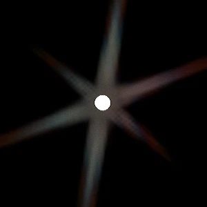
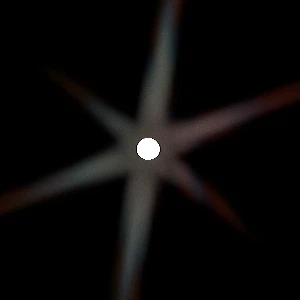
(1 sample vs 4 samples at corners)
Now let's go back inside RenderLensFlare() to implement the final mixing process:
TODO_MIX
[...]

    {
        const FString PassName("LensFlareMix");

        FIntRect MixViewport = FIntRect(
            0,
            0,
            View.ViewRect.Width() / 2,
            View.ViewRect.Height() / 2
        );

        FVector2D BufferSize = FVector2D( MixViewport.Width(), MixViewport.Height() );

        // Create buffer
        FRDGTextureDesc Description = Inputs.Bloom.Texture->Desc;
        Description.Reset();
        Description.Extent = MixViewport.Size();
        Description.Format = PF_FloatRGBA;
        Description.ClearValue = FClearValueBinding(FLinearColor::Transparent);
        FRDGTextureRef MixTexture = GraphBuilder.CreateTexture(Description, *PassName);

        // Shader parameters
        TShaderMapRef<FCustomScreenPassVS> VertexShader(View.ShaderMap);
        TShaderMapRef<FLensFlareBloomMixPS> PixelShader(View.ShaderMap);

        FLensFlareBloomMixPS::FParameters* PassParameters = GraphBuilder.AllocParameters<FLensFlareBloomMixPS::FParameters>();
        PassParameters->Pass.RenderTargets[0]   = FRenderTargetBinding(MixTexture, ERenderTargetLoadAction::ENoAction);
        PassParameters->InputSampler            = BilinearClampSampler;
        PassParameters->GradientTexture         = GWhiteTexture->TextureRHI;
        PassParameters->GradientSampler         = BilinearClampSampler;
        PassParameters->BufferSize              = BufferSize;
        PassParameters->PixelSize               = FVector2D( 1.0f, 1.0f ) / BufferSize;
        PassParameters->InputViewportSize       = BloomInputViewportSize;
        PassParameters->Tint                    = FVector4( PostProcessAsset->Tint );
        PassParameters->Intensity               = PostProcessAsset->Intensity;

        if( PostProcessAsset->Gradient != nullptr )
        {
            const FTextureRHIRef TextureRHI = PostProcessAsset->Gradient->Resource->TextureRHI;
            PassParameters->GradientTexture = TextureRHI;
        }
At this point you should get a sense of déjà vu here given how common that setup is. Nothing special to mention.
Continuing the function:
        // Plug in buffers
        const int32 MixBloomPass = CVarLensFlareRenderBloom.GetValueOnRenderThread();

        PassParameters->MixPass = FIntVector(
            (Inputs.bCompositeWithBloom && MixBloomPass),
            (FlareTexture != nullptr),
            (GlareTexture != nullptr)
        );

        if( Inputs.bCompositeWithBloom && MixBloomPass )
        {
            PassParameters->BloomTexture = Inputs.Bloom.Texture;
        }
        else
        {
            PassParameters->BloomTexture = InputTexture;
        }

        if( FlareTexture != nullptr )
        {
            PassParameters->Pass.InputTexture = FlareTexture;
        }
        else
        {
            PassParameters->Pass.InputTexture = InputTexture;
        }

        if( GlareTexture != nullptr )
        {
            PassParameters->GlareTexture = GlareTexture;
        }
        else
        {
            PassParameters->GlareTexture = InputTexture;
        }
This part focus on making sure the buffers plugged into the shader parameters are valid. Null buffers are not authorized, which is why I choose to setup a IntVector as a group of booleans to know if a buffer is valid or not when sampling it in the shader.
This part could be optimized out by removing all of this if/else chain, but that would mean losing the ability to toggle some effects with the cvars. So adjust the code appropriately if that's what you want.
Last bits:
        // Render
        DrawShaderPass(
            GraphBuilder,
            PassName,
            PassParameters,
            VertexShader,
            PixelShader,
            ClearBlendState,
            MixViewport
        );

        OutputTexture = MixTexture;
        OutputRect = MixViewport;
    }


    ////////////////////////////////////////////////////////////////////////
    // Final Output
    ////////////////////////////////////////////////////////////////////////
    Outputs.Texture = OutputTexture;
    Outputs.Rect    = OutputRect;

} // end of RenderLensFlare()
We perform the final render and then assign the output struct the final texture and its size. The rendering process is done and the engine will use our result from now on.
Now that everything is in place and (should be) running, it's easy to compare timings between the original method and the new one:
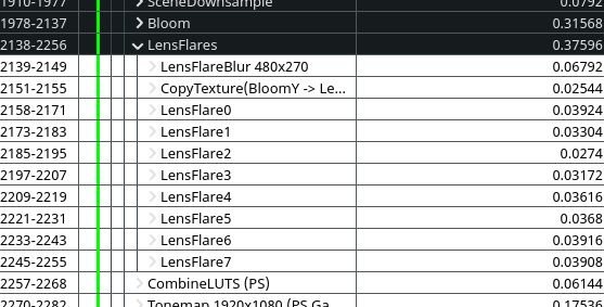
(Original Unreal effect: total ~0.376ms at 1080p)
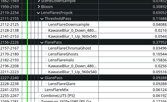
(New effect: total ~0.65ms at 1080p)
The performance measured are based on my RX 5600 XT on Linux with Mesa drivers and the Vulkan backend.
As you can see, the render time is doubled but the effect is much more rich. And for an effect that adds so much to the image without the need of manual work in a scene, I feel it's a good trade-off. We are still below 1ms after all.
I'm pretty sure the default UE4 effect could be optimized by merging the Ghosts generation into a single pass. The bokeh blur is actually quite fast in itself (but has the quality issues I mentioned).
On our side, I think it should be doable to skip the threshold pass and combine it with the downsampled buffer that the engine generates which would save additional time. It won't be as controllable as it is right now which is why I didn't go this way.
I also think some blur pass might be avoided by using more adapted filters when generating/sampling some passes, but as some point I wanted to move on and decided to leave things as-is since performances were already good enough.
Some of the effects could also be moved to compute shaders to take advantage of parallelization/shared memory and speed-up further the rendering time, but I'm not familiar enough with the subject to be sure.
So overall, there still a bit of room for improvement !

It's done !
I didn't expect this subject to take this long to investigate, figure out and even implement. Things started in December 2020 to finish this September 2021. There has been some on and off of course but what a ride !
For the curious minds, take a look at my Twitter thread where I shared most of my progress, including the little joys and other strange bugs. The most difficult part ended up being the Glare effect.
I would also like to give special thanks to:
- Newin
- DeathRay
- Phy
- Nicolas
- Christophe S.
- Gael C.
And of course everybody else who made nice comments on my progress during all the development phase. :)
A little bonus section that focus on a few things I discovered while working on this subject. Hopefully this will be useful for somebody else.
When working with shaders, it is often useful to view the result of a render pass isolated to more easily debug the shader behavior. This can be done by doing a frame capture with a graphic debugger like RenderDoc, but this can be a slow process (especially when iterating).
Fortunately the Unreal Engine has a native tool to display textures directly over the viewport. This can be done by running the following console command:
vis NameOfTheBuffer
The name of the buffer is the same name that was specified for each render pass in the code. So if we want to see the ghosts, we can call:
vis LensFlareGhosts
Which gives the following result:
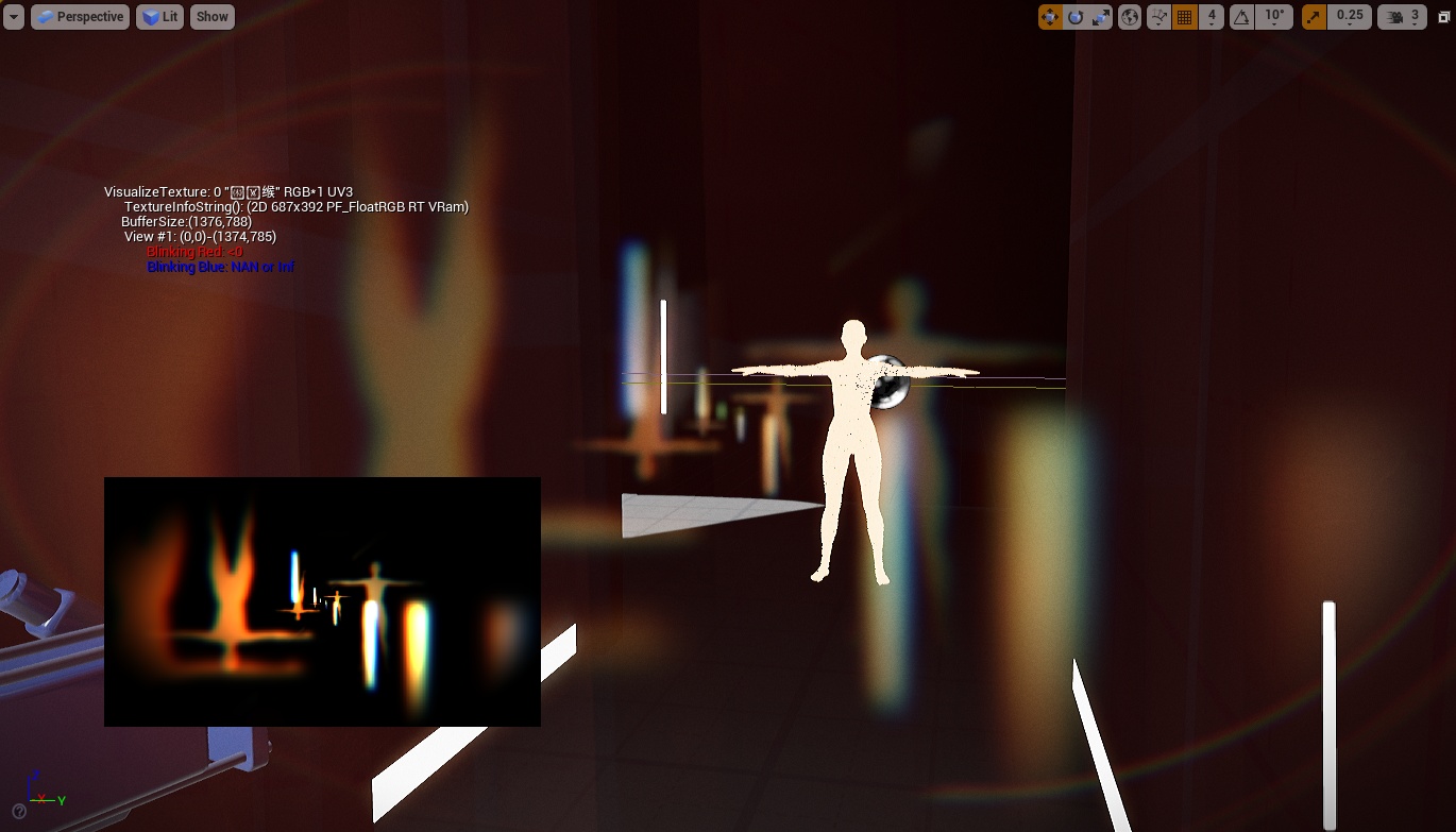
To clear the viewport, simply call:
vis none
For a few more details, check out the RDG documentation. You can also run the vis command as well to print its format.
Several times I mentioned that I had to generate mipmaps to try some things out. While none of my actual code needs it anymore, I initially struggled to figure out the right setup. So I wanted to a least document somewhere how it's done.
There is two things to know in order to get mipmaps: the target buffer must be setup the right way when RDG creates it. Then just ask the engine to generate the mipmaps levels for you after you finished rendering the buffer.
The first step is important because the second one will assert if you didn't configure things properly. The buffer must have a flag that tels the GPU that it can both read and write into it. This is because mipmaps are generated by compute shaders that do both at the same time.
So when building a buffer, add the new flag like so:
FRDGTextureDesc Description = InputTexture->Desc;
Description.Reset();
Description.Extent  = Viewport2.Size();
Description.Format  = PF_FloatRGB;
Description.ClearValue = FClearValueBinding(FLinearColor::Transparent);

// Number of mips you want to generate.
Description.NumMips = 5;

// Flag to tell the engine and GPU this buffer can be both read and write.
// (The |= append the new flag to the existing list.)
Description.TargetableFlags |= ETextureCreateFlags::TexCreate_UAV;

FRDGTextureRef Texture = GraphBuilder.CreateTexture(Description, *PassName);
Perform you render pass normally afterward (like we did with DrawShaderPass()) and then use:
FGenerateMips::Execute( &GraphBuilder, Texture, BilinearBorderSampler );
FGenerateMips is a dedicated class of the engine to build mipmaps for us. You will have to include GenerateMips.h to access it.
Regarding the UAV flag:
An unordered access view (UAV) is a view of an unordered access resource (which can include buffers, textures, and texture arrays, though without multi-sampling). A UAV allows temporally unordered read/write access from multiple threads. This means that this resource type can be read/written simultaneously by multiple threads without generating memory conflicts.
Source: Microsoft documentation.
If you followed this article from start to finish to build your own effect (or the same one) you will end-up with a very, very long file. I found it difficult to manage so I looked into ways to split things up.
I didn't want to make sub-classes to keep the code simple and having multiple .cpp is not really possible (or at least lead to some tedious setup).
Instead, it is possible to have a main .cpp file and have additional .inl file which gets merged together during compilation. What is handy is that you don't have to duplicate includes or anything else since in the end it will act as a single big file.
So in the end I have 4 files:
And inside the .cpp file I just add includes after the main ones:
#include "LensFlareShaders.inl"
#include "LensFlareRendering.inl"
Inside PostProcessSubsystem.cpp I only have the main module functions (like Initialize()) while the actual render functions are all in LensFlareRendering.inl. The namespace that contains all the global shader definitions is inside LensFlareShaders.inl.
In Unreal it is possible to explicitly request the engine to recompile all the shaders (including the global ones).
When iterating on global shaders (.usf) it is very handy to be able to request that at runtime without having to close the game/editor and restart it to force the compilation. This is done by using a little console command. Since I always struggle to find in the official documentation I wanted to note it here:
RecompileShaders changed
This will crawl all the shader files on disk, figure out which one are modified, and recompile them. Make sure to have enabled r.ShaderDevelopmentMode for shader debugging in case you want to catch typos and not crash immediately.
You can also use:
- RecompileShaders all: recompile everything (like first time you run the engine/editor).
- RecompileShaders changed: recompile modified global shader (.usf).
- RecompileShaders global: recompile all global shader (.usf).
- RecompileShaders material [name]: recompile a specific material.
- RecompileShaders platform [name]: recompile changed shaders for a specific platform.
It might be useful to execute console commands without passing by the console itself. In my case I have a debug UI which looks like this:
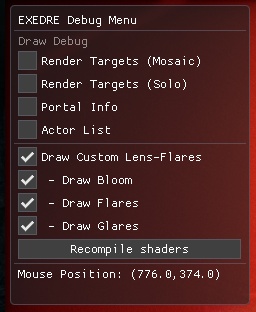
When clicking on one of the checkboxes related to the lens-flares it actually executes a console command. This is very handy to debug stuff and do comparisons without having to look at the console to type the command.
So to run a command from your game code, simply call:
const FString Command = "yourCommand";
GEngine->Exec( GetWorld(), *Command );
Here is another example with a cvar made during this article:
// bDrawGlare is a boolean from my debug UI class
const FString Command = "r.LensFlare.RenderGlare " + FString::FromInt( bDrawGlare );
GEngine->Exec( GetWorld(), *Command );
Below is a (long) list of various papers, posts and examples that helped the writing of this article:
Games:
Papers:
Articles:
Examples: